Eureka AIR delivers breakthrough ideas for toughest innovation challenges, trusted by R&D personnel around the world.

Oil casing pipe joint anti-thread-gluing coating and preparation method thereof

A oil casing, anti-sticking technology, applied in the direction of pipes/pipe joints/fittings, coatings, anti-corrosion coatings, etc., can solve problems such as heavy metal powder pollution

Active Publication Date: 2015-04-15
BAOSHAN IRON & STEEL CO LTD
View PDF8 Cites 11 Cited by
  • Summary
  • Abstract
  • Description
  • Claims
  • Application Information

AI Technical Summary

Problems solved by technology

[0011] The object of the present invention is to provide an anti-sticking coating for threaded joints of oil casing pipes and its preparation method. By spraying the coating of the present invention on the surface of phosphate-treated oil casing joints, the oil casing joints can be obtained without thread grease anti-sticking. coating, which solves the environmental pollution caused by heavy metal powder in thread grease

Method used


Image

  • Oil casing pipe joint anti-thread-gluing coating and preparation method thereof
  • Oil casing pipe joint anti-thread-gluing coating and preparation method thereof
  • Oil casing pipe joint anti-thread-gluing coating and preparation method thereof

Examples


Embodiment 1

[0051] Coating composition (weight percent)

[0052] 49.8% polyamideimide, 10% polytetrafluoroethylene, 30% modified molybdenum disulfide, 5% modified titanium dioxide, 5% calcium stearate, 0.1% leveling agent, 0.1% wetting agent, mixed solvent The dosage is 3 times the mass of the above components.

[0053] Coating process: the pressure of the spray gun is 0.25MPa, and the temperature is kept at 280°C for 0.3 hours in a drying oven.

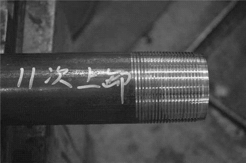
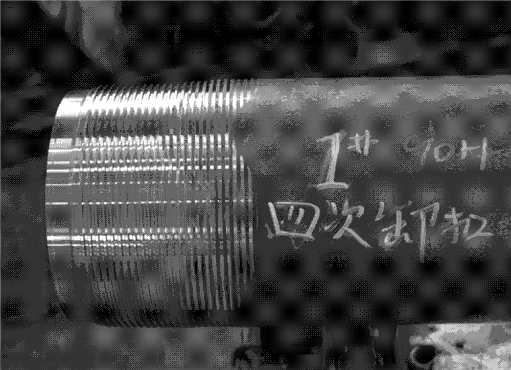
[0054] Results: After the above treatment, the bonding strength between the coating and the oil pipe joint of P110 steel grade is grade 1; there is no sticking phenomenon in the make-up and breakout 11 times; there is no rust point in the neutral salt spray test for 100 hours.

Embodiment 2

[0056] 30.89% polyamideimide, 7% polytetrafluoroethylene, 49% modified molybdenum disulfide, 10% modified titanium dioxide, 3% calcium stearate, 0.01% leveling agent, 0.1% wetting agent, mixed solvent The dosage is 4 times the mass of the above components.

[0057] Coating process: the pressure of the spray gun is 0.25MPa, and the temperature is kept at 280°C for 0.1 hour in a drying oven.

[0058] Results: After the above treatment, the bonding strength between the coating and the oil pipe joint of P110 steel grade is grade 1; there is no sticking phenomenon in the make-up and breakout 11 times; there is no rust point in the neutral salt spray test for 100 hours.

Embodiment 3

[0060] 57.89% polyamideimide, 4% polytetrafluoroethylene, 32% modified molybdenum disulfide, 5% modified titanium dioxide, 1% calcium stearate, 0.1% leveling agent, 0.01% wetting agent, mixed solvent The dosage is 3.5 times the mass of the above components.

[0061] Coating process: the pressure of the spray gun is 0.25MPa, and the temperature is kept at 250°C for 0.1 hour in a drying oven.

[0062] Results: After the above treatment, the bonding strength between the coating and the oil pipe joint of BG110SS steel grade was grade 1; there was no sticking phenomenon in the make-up and breakout 11 times; there was no rust point in the neutral salt spray test for 100 hours.


PUM


Abstract

An anti-galling coating for a threaded joint of an oil casing. The mass percentages of the components of the coating are: organic binder 30-60 wt%, solid lubricant 30-60 wt%, anticorrosive agent 6-15 wt%, leveling agent 0.01-0.1 wt%, wetting agent 0.01-0.1 wt% and mixed solvent in addition. The organic binder is polyamide-imide liquid resin with a solid content of 38-42 wt%. The solid lubricant is any one of molybdenum disulphide and tungsten disulfide, or a combination of molybdenum disulfide or tungsten disulfide and polytetrafluoroethylene. Preferably the solid lubricant and the anticorrosive agent are surface modified with silane coupling agent. The anti-galling coating is obtained by spraying the coating on the surface of an oil casing joint processed with phosphate, and the environmental pollution caused by heavy metal powder in thread compounds is avoided.

Description

technical field [0001] The invention relates to the technical field of surface treatment, in particular to an anti-stick coating for an oil-casing joint and a preparation method thereof. Background technique [0002] Oil and gas exploration and development must use oil and casing products. The casing is threaded to form a casing string to form an oil production channel, and the oil pipe is threaded to form a tubing string for oil production. [0003] The oil casing joint is composed of internal thread and external thread, and the thread is tightened and loosened by make-up and breakout during use. The threaded joint is equivalent to a pair of friction pairs. When the surface of the internal thread and the external thread are in contact with each other, from a microscopic point of view, the actual contact area of ​​the two contact bodies is only on a few asperities on the joint surface. Due to the high contact pressure, it causes The asperities are plastically deformed and w...

Claims


Application Information

Patent Timeline
IPC IPC(8): C09D179/08C09D5/08C09D7/12C09D7/80
CPCC09D5/084C09D5/086C09D179/08C09D7/62C08L27/18C08K13/06C08K2003/3045C08K2003/2241C08K5/098C08G73/14C08K2003/3009F16L15/00C08K3/22C08K3/30C08L33/16C08L83/12C09D127/18F16L15/04
Inventor 王琍
Owner BAOSHAN IRON & STEEL CO LTD
Why Eureka
Eureka Blog
Learn More