Fiber optic temperature sensor based on sealed micro cavity gas thermal effect and manufacturing method of fiber optic temperature sensor

An optical fiber temperature and sensor technology, applied in the direction of thermometers, thermometers, instruments, etc. with physical/chemical changes, can solve the problems of difficulty in mass production, the limitation of the degree of freedom of temperature sensitivity design, and achieve good consistency, low cost, The effect of large design freedom

Active Publication Date: 2015-04-15
TIANJIN UNIV
View PDF4 Cites 22 Cited by
  • Summary
  • Abstract
  • Description
  • Claims
  • Application Information

AI Technical Summary

Problems solved by technology

However, the above two types of optical fiber temperature sensors are all made by hand, and it is difficult to achieve mass production
And because its temperature sensitivity is ...

Method used


Image

  • Fiber optic temperature sensor based on sealed micro cavity gas thermal effect and manufacturing method of fiber optic temperature sensor
  • Fiber optic temperature sensor based on sealed micro cavity gas thermal effect and manufacturing method of fiber optic temperature sensor
  • Fiber optic temperature sensor based on sealed micro cavity gas thermal effect and manufacturing method of fiber optic temperature sensor

Examples


Embodiment 1

[0033] Embodiment 1: The structure and manufacture of an optical fiber temperature sensor based on the gas thermal effect of a closed microcavity.

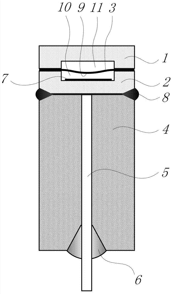
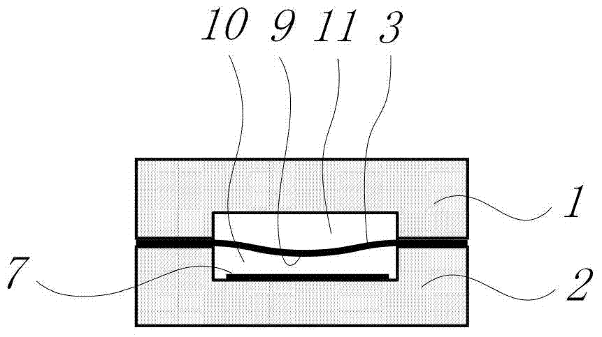
[0034] like figure 1 As shown, the sensor structure includes a sensor head chip, a sensor body 4 and an optical fiber 5 . figure 2 Shown is a three-layer sensor head chip manufactured by anodic bonding process, which includes a first Pyrex glass wafer 1 , a single crystal silicon wafer 3 and a second Pyrex glass wafer 2 . The specific production process is: using HF and HNO 3 The solution etches out the shallow pit array on the Pyrex glass wafer 2 as the cavity of the Fapo microcavity 10, and plating Ta at the bottom of the shallow pit 2 o 5 reflective film7. Under the condition of vacuum environment (that is, 0kpa), the second Pyrex glass wafer with the shallow pit array etched and the monocrystalline silicon wafer 3 are fused by anodic bonding to form the Fab microcavity 10, wherein Ta 2 o 5 The reflective film 7 and the ...

Embodiment 2

[0037] Example 2: Temperature measurement process of optical fiber temperature sensor based on thermal effect of airtight microcavity

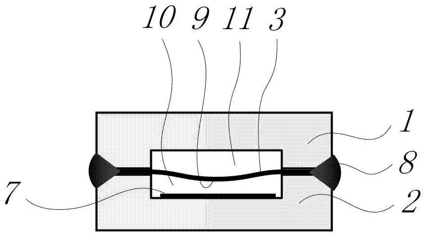
[0038] Figure 4 Shown is a schematic diagram of the sensor temperature measurement principle. The first Pyrex glass wafer 1 corrodes the shallow pit and the monocrystalline silicon wafer 3 to form a Fapp microcavity 10, and the first Pyrex glass wafer 1 etches the shallow pit array and the monocrystalline silicon wafer 3 to form an air chamber. microcavity11. The single crystal silicon wafer 3 is sandwiched between the Fapp microcavity 10 and the air microcavity 11 . By separately controlling the production environment pressures of the two cavities, different molar quantities of air molecules 12 exist in the two cavities, which is visually manifested as a fixed pressure difference P in the micro cavities on both sides of the single crystal silicon wafer 3 . Therefore, under the action of the pressure difference, the single crystal silicon ...

Embodiment 3

[0046] Example 3: Optical fiber temperature sensor experiment and microcavity cavity length demodulation based on the thermal effect of airtight microcavity

[0047] The cavity length demodulation system based on low-coherence interference demodulation is shown in Fig. Figure 5 shown. The process of cavity length demodulation is: the light emitted by the broadband light source 17 (the broadband light source is a white light LED, xenon lamp or halogen lamp) is coupled into the transmission fiber 19, and enters a 3dB 2×1 coupler 18 or an optical circulator, From the other end, it is incident on the sensor 20 through the transmission fiber 19 . The light signal reflected by the sensor 20 passes through the 3dB 2×1 coupler 18 again and then enters the Fab cavity length demodulator 21 to obtain the demodulated low-coherence interference original signal 24, as shown in Image 6 shown. The low-coherence interference original signal 24 is transmitted to the computer 23 through the...


PUM

PropertyMeasurementUnit
Diameteraaaaaaaaaa
Depthaaaaaaaaaa

Abstract

The invention discloses a fiber optic temperature sensor based on a sealed micro cavity gas thermal effect and a manufacturing method of the fiber optic temperature sensor. A sensor structure comprises a Fabry-Perot micro cavity and an air micro cavity, and the two micro cavities are partitioned through a thin silicon membrane. The atmospheric pressure environments of the two micro cavities are respectively controlled in the sensor manufacturing process, so that the two micro cavities have pressure difference. When the temperature changes, according to an ideal gas state equation, the atmospheric pressure inside the two micro cavities is changed, so that a silicon wafer in the middle of the two micro cavities is deformed because of the change of the pressure difference. At the same time the inner surface of the silicon wafer and the reflection surface inside the Fabry-Perot micro cavity form a low-fineness Fabry-Perot interferometer, the deformation of the membrane is just the length change of the Fabry-Perot micro cavity, and temperature measurement is achieved by demodulating the length change of the cavity. Compared with the prior art, the temperature sensitivity of the sensor disclosed by the invention can be flexibly controlled by designing the diameter, the temperature and the pressure difference of the silicon wafer, and expected temperature sensitivity is achieved. In addition, the in-batch production of the senor is beneficial to cost reduction, and commercialization can be realized.

Description

technical field [0001] The invention relates to the technical field of optical fiber sensing, in particular to an optical fiber temperature sensor based on the gas thermal effect of a closed microcavity and a manufacturing method thereof. Background technique [0002] Due to its small size, high precision, superior performance and adaptability to harsh environments, the fiber optic F-P temperature sensor has attracted more and more attention from researchers at home and abroad. In recent years, there are mainly two types of fiber-optic F-P temperature sensors: air-gap type and medium-filled type. The optical path difference of the air-gap Fapier temperature sensor is determined by the cavity length of the Fapocket cavity, and its temperature sensing principle lies in the thermal expansion effect of the cavity length. So far, researchers at home and abroad have proposed a variety of air-gap Fappau temperature sensors, for example, J.Wang et al. (J.Wang, B.Dong, E.Lally, J.Go...

Claims


Application Information

Patent Timeline
IPC IPC(8): G01K11/32
Inventor 刘铁根江俊峰尹金德刘琨王双邹盛亮秦尊琪吴凡
Owner TIANJIN UNIV
Why Eureka
Try Eureka