Stainless steel pipeline welding connection method and center-adjustable connection clamp

A connection fixture and welding connection technology, applied in the direction of welding/welding/cutting items, welding equipment, welding equipment, etc., can solve the problems of difficult welding, difficult to grasp and control, and difficult to control the deformation, so as to ensure the welding operation The effect of reducing the length and joint defect rate and avoiding joint defects

Inactive Publication Date: 2015-04-29
LONGKOU CIMC RAFFLES OFFSHORE +2
View PDF10 Cites 22 Cited by
  • Summary
  • Abstract
  • Description
  • Claims
  • Application Information

AI Technical Summary

Problems solved by technology

However, the welding of stainless steel pipes often faces two difficult-to-control problems: oxidation on the back, and deformation during welding
[0004] 1. Create a pure inert gas protective atmosphere in the area affected by welding, such as using industrial high-purity argon. This method is the most effective but the least efficient;
[0005] 2. Use self-shielded welding wire, which releases protective gas and slag during welding. This method is only effective for the root weld, because once it reaches the second layer, there will be no protective atmosphere in the pipeline. In this way, the inner wall of the pipeline will still be oxidized during welding, and at the same time, this method will generate slag, which will directly affect the cleanliness inside the pipeline;
[0010] Compared with other materials, stainless steel pipes have the following characteristics: larger coefficie

Method used


Image

  • Stainless steel pipeline welding connection method and center-adjustable connection clamp
  • Stainless steel pipeline welding connection method and center-adjustable connection clamp
  • Stainless steel pipeline welding connection method and center-adjustable connection clamp

Examples


Embodiment approach

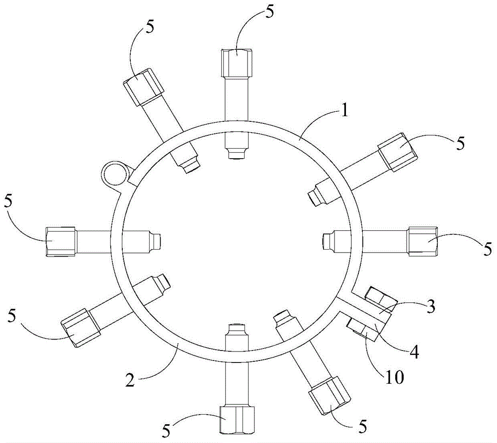
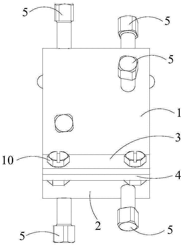
[0047] Such as figure 1 with figure 2 As shown, the first embodiment of the adjustable center connection clamp of the present invention includes a clamp unit. The fixture unit includes an upper half-ring steel plate 1, a lower half-ring steel plate 2 and a plurality of jacking bolts 5. One end of the upper half-ring steel plate 1 and the lower half-ring steel plate 2 are hingedly connected, and the other end is detachably connected together, so that the upper half-ring The steel plate 1 and the lower half-ring steel plate 2 form an accommodating space. A plurality of tightening bolts 5 are respectively installed in the accommodating space formed by the upper half-ring steel plate 1 and the lower half-ring steel plate 2, and the inner ends of the tightening bolts 5 protrude into the accommodating space.

[0048] Further, the other end of the above-mentioned upper half-ring steel plate 1 has an upper pressing plate 3, and the other end of the lower half-ring steel plate 2 has...

Embodiment approach 2

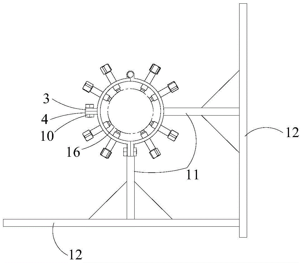
[0054] Such as image 3 , Figure 4 with Figure 5 As shown, the second embodiment of the adjustable center connection clamp of the present invention comprises two independent clamp units. The specific structure of each clamp unit is the same as that of the first embodiment, and will not be repeated here.

[0055] The two fixture units are respectively fixed on two supports 11 by welding, the supports 11 are fixed on the foundation 12, the supports 11 can be temporary supports or formal supports on site, and the base 12 is a large mass object near the site such as a steel plate on a ship or ground. When in use, each clamping bolt 5 on the two fixture units can be screwed in or out, so that two adjacent stainless steel pipes can be positioned in a coaxial state. The function of the support 11 is to limit the relative position between the two adjustable connecting fixture units and prevent them from moving during the welding process. After the stainless steel pipe is welded,...

Embodiment approach 3

[0059] Such as Figure 7 , Figure 8 with Figure 9 As shown, the third embodiment of the adjustable joint clamp of the present invention includes two clamp units. It differs from the second embodiment only in that: the two clamp units are fixedly connected by steel bars 9 . The following takes three steel bars 9 parallel to each other and evenly distributed around the adjustable center connecting fixture as an example to illustrate as follows:

[0060] One end of a steel bar 9 is welded to the upper half-ring steel plate 1 of one of the fixture units, and the other end is welded to the upper half-ring steel plate 1 of the other fixture unit; one end of the other two steel bars 9 is welded to one of them respectively. On the lower half-ring steel plate 2 of the fixture unit, the other end is respectively welded on the lower half-ring steel plate 2 of another fixture unit. The steel bar 9 can be a square steel or a fixture with other cross-sectional shapes. The number of s...


PUM

PropertyMeasurementUnit
Diameteraaaaaaaaaa

Abstract

The invention discloses a stainless steel pipeline welding connection method and a center-adjustable connection clamp. The stainless steel pipeline welding connection method comprises the following steps: A, performing slope holes in the end parts of two or more stainless steel pipelines; B, coaxially arranging the stainless steel pipelines with the preformed slope holes, and filling the space between the preformed slope holes of the every two adjacent stainless steel pipelines with stainless steel sheets and stainless steel wires; C, coating the section, near the slope hole, of each stainless steel pipeline with a layer of anti-splashing agent for welding and the like before welding to wrap and cover the section, near the slope hole, of the stainless steel pipeline; D, mounting an argon protection device filled with argon in the stainless steel pipeline at the to-be-welded part; E, finishing the welding process, cooling the stainless steel pipeline to lower than 50 DEG C, and dismounting the center-adjustable connection clamp. According to the method, the position welding operation which has to be carried out in a conventional method can be avoided, the damage to base metal due to position welding can be completely avoided, the operation time for pipeline assembly and welding is shortened, and the overall precision of a pipeline product is guaranteed.

Description

technical field [0001] The invention relates to the field of welding technology, in particular to a stainless steel pipe welding connection method and an adjustable connection fixture. Background technique [0002] At present, in the construction of marine engineering, a large number of pipeline installation and welding work will be involved, among which stainless steel pipe is a common kind of pipeline. However, the welding of stainless steel pipes often faces two difficult-to-control problems: oxidation of the back, and deformation during welding. [0003] Stainless steel is a metal that is easily oxidized during welding. If pickling and passivation treatment is not carried out after mild oxidation, the corrosion resistance of the oxidized area will be significantly reduced. In particular, when most pipes are welded, if the back is oxidized , It is very difficult to handle and the effect is not good, so in the welding process, it is necessary to ensure that the area affec...

Claims


Application Information

Patent Timeline
IPC IPC(8): B23K9/173B23K9/235B23K9/32
CPCB23K9/173B23K9/00B23K9/0282B23K9/235B23K33/004B23K37/0533B23K2101/06B23K2103/04
Inventor 时群超
Owner LONGKOU CIMC RAFFLES OFFSHORE
Why Eureka
Try Eureka