Semiconductor LED chip and manufacturing method thereof

A light-emitting diode and semiconductor technology, applied in semiconductor devices, electrical components, circuits, etc., can solve the problems of reducing the conductivity of n-type semiconductors, uneven current distribution, and reducing the luminous efficiency of chips, so as to improve light extraction efficiency and reduce epitaxy. The effect of growth cost and high transmittance

Active Publication Date: 2015-04-29
SHANDONG INSPUR HUAGUANG OPTOELECTRONICS
View PDF3 Cites 22 Cited by
  • Summary
  • Abstract
  • Description
  • Claims
  • Application Information

AI Technical Summary

Problems solved by technology

This brings a new problem: the absorption of light by the n-type semiconductor layer
However, using these two methods alone will reduce the conductivity of the n-type semiconductor, which will lead to uneven current distribution when the chip is working, and reduce the luminous efficiency of the chip.

Method used


Image

  • Semiconductor LED chip and manufacturing method thereof
  • Semiconductor LED chip and manufacturing method thereof
  • Semiconductor LED chip and manufacturing method thereof

Examples


Embodiment 1

[0053] A semiconductor light-emitting diode chip, its structure from top to bottom is a transparent conductive layer 600, an n-type semiconductor layer 213, an active layer 212, a p-type semiconductor layer 211, a p-type contact layer 300, a dielectric insulating layer 400, and a plurality of The n-type contact layer 500 of the through hole is bonded to the metal layer 510 , the conductive substrate 520 , and the n-electrode 530 . The n-type contact layer 500 runs through the entire epitaxial layer 210 and is in contact with the transparent conductive layer 600 . The surface of the chip has a window 230 , the p-electrode 310 is located in the window area, and the p-electrode 310 is in contact with the p-type contact layer 300 . The n-type semiconductor layer and the p-type semiconductor layer used are gallium nitride (GaN), and the active layer is made of indium gallium nitride (InGaN) material.

[0054] The production method comprises the following steps, such as figure 2 ...

Embodiment 2

[0067] As described in Embodiment 1, the difference is that the depth of the through hole 220 only reaches the middle of the n-type semiconductor layer, as Figure 4 shown. The n-type contact layer 500 is in contact with the n-type semiconductor layer 213 without penetrating through the entire epitaxial layer. The material of the transparent conductive layer is zinc oxide (ZnO), and the thickness is

Embodiment 3

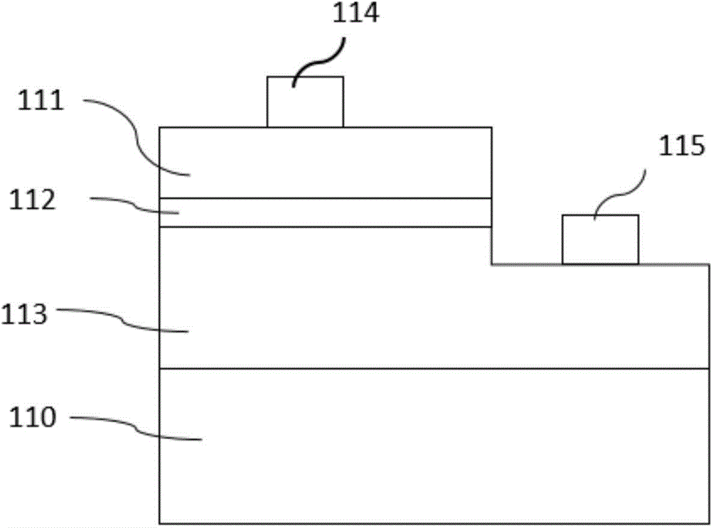
[0072] As described in Embodiment 1, the difference is that the conductive substrate 520 is replaced by an insulating substrate 521, the insulating substrate is sapphire, and there are two windows on the chip surface, one of which is a p-electrode window, and the p-electrode and The p-type contact layer is in contact to realize the electrical connection between the p-electrode and the p-type semiconductor layer; the other window 240 is an n-electrode window, and an n-electrode is formed on the n-type contact layer to realize the electrical connection between the n-electrode and the n-type semiconductor layer. The p and n electrodes are located on the same side of the chip. structured as Figure 5 shown.

[0073] Preparation:

[0074] The first step to the fifth step are identical with embodiment 1;

[0075] In the sixth step, the epitaxial wafer is bonded to the insulating substrate 521, and the substrate 200 is removed by a combination of mechanical grinding and dry etchin...


PUM


Abstract

The invention relates to a semiconductor LED (Light-Emitting Diode) chip and a manufacturing method thereof. The semiconductor LED chip comprises a transparent conductive layer, an n-type semiconductor layer, an active layer, a p-type semiconductor layer, a p-type contact layer, a dielectric insulating layer, an n-type contact layer, a bonding metal layer and a substrate, wherein the n-type contact layer reaches the interior of the n-type semiconductor layer or penetrates through the whole n-type semiconductor layer by virtue of through holes penetrating through each layer at the upper part of the n-type contact layer. The manufacturing method for the semiconductor LED chip comprises the following steps of manufacturing an epitaxial wafer, bonding the epitaxial wafer to another conductive or insulating substrate, removing a growing substrate, and manufacturing the transparent conductive layer on the surface of the n-type semiconductor layer. According to the semiconductor LED chip and the manufacturing method thereof, a transparent conductive layer material is adopted as a current expansion layer, so that the thickness or doping concentration of the n-type semiconductor layer is reduced, light is favorably absorbed by an n-type material, and the light extraction efficiency of the LED chip is improved.

Description

technical field [0001] The invention relates to a semiconductor light emitting diode chip and a manufacturing method thereof, belonging to the field of semiconductor light emitting diodes. Background technique [0002] In recent years, as a new type of light source, light emitting diode (LED for short) has been widely used in various fields of social life, such as outdoor display, instrument indication, general lighting and so on. [0003] The existing LED structure includes a substrate 110, a p-type semiconductor layer 111, an active layer 112, an n-type semiconductor layer 113, a p-electrode 114 and an n-electrode 115. When a voltage is applied between the p-electrode 114 and the n-electrode 115, the current flows from The p-electrodes 114 to n-electrodes 115 perform electro-optical conversion in the active layer 112 . Such as figure 1 shown. Since the p and n electrodes are located on the same side of the chip, when the chip is working, the injected current is unevenly...

Claims


Application Information

Patent Timeline
Patent Type & Authority Applications(China)
IPC IPC(8): H01L33/42H01L33/00
CPCH01L33/0093H01L33/382H01L33/42
Inventor 徐化勇徐现刚徐明升沈燕
Owner SHANDONG INSPUR HUAGUANG OPTOELECTRONICS
Why Eureka
Try Eureka