Solar module frame and solar panel module based on 3D printing technology

A solar module, 3D printing technology, applied in electrical components, photovoltaic power generation, photovoltaic modules, etc., can solve problems such as soil erosion, power generation failure, paralysis, etc., to achieve the effect of maintaining the same strength, simple structure, and reducing weight

Active Publication Date: 2015-05-06
江阴市广业光电科技有限公司
View PDF5 Cites 0 Cited by
  • Summary
  • Abstract
  • Description
  • Claims
  • Application Information

AI Technical Summary

Problems solved by technology

[0003] For example, in the northwest region, the ground power station is blown by the wind for a long time during operation, which will cause slight deformation of the overall solar module array, and under stress extrusion conditions, it will cause hidden cracks in the power generation unit. It is very e

Method used


Image

  • Solar module frame and solar panel module based on 3D printing technology
  • Solar module frame and solar panel module based on 3D printing technology
  • Solar module frame and solar panel module based on 3D printing technology

Examples


Example Embodiment

[0031] Example 1

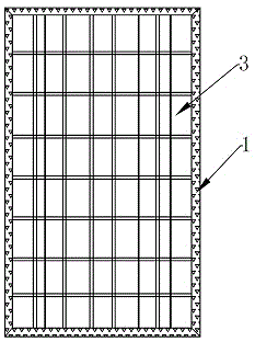
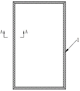
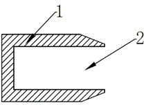
[0032] Such as Figure 1 to Figure 4 As shown, the solar module frame 1 based on 3D printing technology of embodiment 1, the inner surface of the solar module frame 1 is provided with a module card slot 2 for embedding the solar module 3, and the outer surface of the solar module frame 1 is provided with a first-level blind In the hole 4, the bottom surface of the primary blind hole 4 is provided with secondary blind holes 5 at intervals, and the apertures of the secondary blind holes 5 are evenly distributed on the bottom surface of the primary blind hole 4.

[0033] In this embodiment, the aperture width of the primary blind holes 4 is not greater than 1 / 5 of the width of the corresponding solar module frame 1; the primary blind holes 4 are arranged in a matrix on the outer surface of the solar module frame 1, and the secondary blind holes 5 The shape and size of the first-level blind hole 4 are spherical and the first-level blind hole 4 located on the outer s...

Example Embodiment

[0035] Example 2

[0036] Such as Figure 5 As shown, the difference between Embodiment 2 and Embodiment 1 is that the first-level blind holes 4 in two adjacent rows are arranged in a staggered arrangement; the second-level blind holes 5 are in a regular quadrangular pyramid shape, and the bottom surface of the first-level blind holes 4 is composed of several corresponding A honeycomb grid surface composed of squares.

[0037] In the honeycomb grid surface formed by the combination of several corresponding squares, the square apertures in two adjacent rows can be arranged in a staggered manner. The tensile strength of the frame of this structural component is about 215MPa.

Example Embodiment

[0038] Example 3

[0039] Such as Image 6 As shown, the difference between Embodiment 3 and Embodiment 1 is that the first-level blind hole 4 includes a first-level blind hole 4-1 and a second-level blind hole 4-2. The aperture area is larger than the aperture area of ​​the second-level blind hole 4-2. The first-level blind holes 4-1 and the second-level blind holes 4-2 are both arranged in a matrix on the outer surface of the solar module frame 1. The second-level blind hole 4-2 is set at the intersection of four adjacent first-level blind holes 4-1 in a square arrangement; the second-level blind hole 5 is a regular hexagonal pyramid, and the first-level blind hole The bottom surfaces of the holes of 4-1 and the second-level blind hole 4-2 are both honeycomb grid surfaces composed of a number of regular hexagons. The tensile strength of the frame of the structural component is about 210MPa.


PUM

PropertyMeasurementUnit
Tensile strengthaaaaaaaaaa

Abstract

The invention discloses a solar module frame and a solar panel module based on a 3D printing technology. A module slot for embedding a solar module is formed in the inner surface of the solar module frame, first-level blind holes are formed in the outer surface of the solar module frame at intervals, second-level blind holes are formed in the bottom face of the first-level blind holes at intervals, and orifices of the second-level blind holes are evenly distributed on the bottom face of the first-level blind holes. The solar module frame is simple in structure, the first-level blind holes and the second-level blind holes are formed in the solar module frame to enable the frame to be of a honeycomb structure, the perfect forming capability of the 3D printing technology can be utilized, metal alloy powder is condensed to be an almost hollow high-strength dynamic structure through laser, materials are saved obviously, the weight is reduced, and the strength is kept unchanged and even become better.

Description

technical field [0001] The invention relates to a solar module frame, in particular to a solar module frame and a solar panel assembly based on 3D printing technology. Background technique [0002] As one of the important components of the photovoltaic power generation system, solar modules are generally installed on the ground or on roofs that are easy to receive sunlight. However, in the vast China, areas with superior lighting conditions are mainly distributed in the northwest, west and central regions. Not only the terrain It is complex, interlaced with mountains, hills, basins, and Gobi, and the natural conditions are changeable, such as rainy, ice and snow, storms, and droughts. Any combination of terrain and weather and climate factors will affect the working stability and power generation efficiency of solar modules. [0003] For example, in the northwest region, the ground power station is blown by the wind for a long time during operation, which will cause sli...

Claims


Application Information

Patent Timeline
IPC IPC(8): H02S30/10
CPCH02S30/00Y02E10/50
Inventor 杨雷章永华
Owner 江阴市广业光电科技有限公司
Why Eureka
Try Eureka