

On-line optical fiber grating preparing system
A technology for preparing systems and fiber gratings, applied in cladding fibers, optical waveguides, optical mechanical equipment, etc., can solve the problems of laser beam uniformity, laser pulse stability, low coherence of laser beam aiming point stability, and poor quality of grating arrays. High reflectivity, affecting grating consistency, etc., to achieve high reflectivity consistency, good grating spectral shape, good uniformity and stability
- Summary
- Abstract
- Description
- Claims
- Application Information
AI Technical Summary
Problems solved by technology
Method used
Image

Examples
Embodiment Construction
[0020] Embodiments of the present invention will be further described below in conjunction with the accompanying drawings.
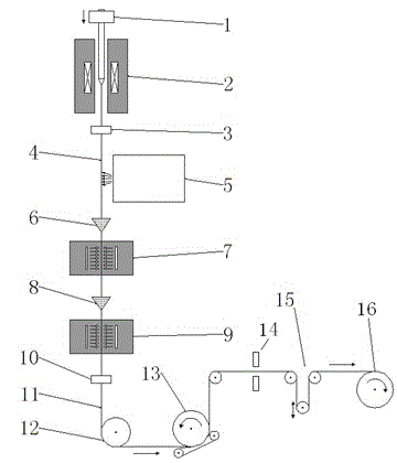
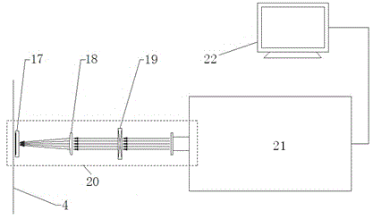
[0021] It consists of a wire drawing tower and a writing grating device, including a wire drawing furnace 2 and a preform clamping and feeding device 1 installed above the wire drawing furnace. A bare optical fiber caliper 3 is installed below the outlet of the wire drawing furnace. The writing grating device 5 is installed below the bare optical fiber 4, and the first-level coater 6, the first-level UV curing furnace 7, the second-level coater 8 and the second-level UV curing furnace are arranged in sequence below the writing grating device along the vertical downward direction of the bare optical fiber 4. Curing furnace 9, an optical fiber caliper 10 is installed under the secondary ultraviolet curing furnace to detect the outer diameter of the coated optical fiber 11, the coated optical fiber is then transferred to the spinning wheel 13 through the ten...
PUM
| Property | Measurement | Unit |
|---|---|---|
| Pulse width | aaaaa | aaaaa |
Abstract
Description
Claims
Application Information