Anaerobic reaction tank for processing intensive cattle farm excreta

An anaerobic reaction tank and excrement technology, which is applied in the fields of excreting fertilizers, adapting to climate change, and treating biological organic parts, etc. It can solve the problems of inability to realize material turnover and stirring, inability to solve complete fermentation, increase equipment and energy consumption, etc. , to achieve the effect of easy automatic control, good heat and mass transfer effect, and small footprint

Inactive Publication Date: 2015-05-27
XUZHOU INSTITUTE OF TECHNOLOGY
View PDF9 Cites 6 Cited by
  • Summary
  • Abstract
  • Description
  • Claims
  • Application Information

AI Technical Summary

Problems solved by technology

This utility model eliminates the mutual restriction between the acidification phase and the methane phase, but when feeding into the reactor, the residue needs to be crushed and slurried, and regular pneumatic stirring is required during the reaction process, which increases the equipment and energy consumption
[0004] In the patent "A dry fermentation device and method for preparing biogas by using high-concentration solid raw materials" (CN201310049692.4), a vertical fermentation device is used to dry-ferment biogas for high-concentration solid raw materials. Rods and arc-shaped push shovels, which cannot realize the turning and stirring of materials, and cannot solve the complete fermentation of all materials
In the patent "dry anaerobic treatment method of kitchen waste and its device (CN201410554673.1)", according to the characteristics of kitchen waste, a dry anaerobic process is used to treat kitchen waste. Water device, but it does not involve the plowing of materials, and the device for stirring and sending out materials after fermentation

Method used


Image

  • Anaerobic reaction tank for processing intensive cattle farm excreta
  • Anaerobic reaction tank for processing intensive cattle farm excreta
  • Anaerobic reaction tank for processing intensive cattle farm excreta

Examples


Embodiment 1

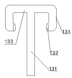
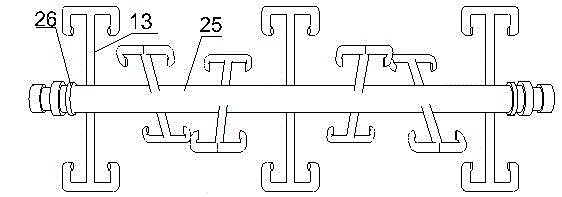
[0032] Such as figure 1 As shown, a kind of anaerobic reaction tank for processing intensive cattle farm excreta, the outer layer of the anaerobic reaction tank 19 is designed with a jacket 9 structure, and the inside of the anaerobic reaction tank is provided with a stirring plate 13, such as figure 2 As shown, the stirring plate 13 is composed of a stirring plate main rod 131, a stirring plate port 132, a stirring plate strut 133 and a stirring plate wing rod 134. The stirring plate main rod 131 is fixed on the rotating shaft 25, and the two ends of the rotating shaft are provided with seals. Ring 26, and connected with the tank body through bearings. The anaerobic reaction tank adopts a horizontal design with a length-to-diameter ratio of 1:3.4. Stirring plate 13 adopts fluororesin as the outer lining, and the thickness of the outer lining is 2 mm. The section of the port 132 of the stirring plate is circular; the distance between the jacket and the body of the anaerobic...

Embodiment 2

[0036] The present embodiment adopts the anaerobic reaction tank of embodiment 1 to process intensive cattle farm excrement, and the size of the anaerobic reaction tank used is as follows:

[0037] The diameter-to-length ratio is: D:H=1:3.4; the geometric dimension of the elliptical head is: h 1 =600mm (surface length); h 0 =40mm (straight edge length); inner surface area of ​​oval head =6.41m 2 ; Ellipse head volume = 1.93m 3 ; The geometric dimension of the cylinder is: H=6391mm (length); the inner surface area of ​​the cylinder is 39.82m 2 ;Cylinder volume 23.86m 3 , labeled as Figure 6 shown.

[0038] In order for the equipment to function properly, routine fixing and piping connections are required, such as Figure 7 As shown, the anaerobic reaction tank 19 of embodiment 1 is fixed between the two left and right bearing supports 16 through the bearing 8, the other end of the bearing 8 is connected with the shaft coupling 7, and the variable speed motor 2 is located...

Embodiment 3

[0053] In order to test the treatment effect of the anaerobic reaction tank designed by the present invention, the treatment equipment and technology of Example 2 are compared with the treatment results of traditional equipment, and the results are improved in product quality, shortened fermentation time, and product in physical chemistry and biology. There are advantages in terms of academic nature:

[0054] 1. Compared with traditional equipment processing, the quality of the product is good or bad

[0055] By screening the obtained ideal fermentation bacteria, comparing and verifying the processing results with traditional equipment, analyzing the changes in the physicochemical and biological properties of metabolites during the fermentation process, and conducting productive comparative tests, the experimental results are shown in Table 1.

[0056] Table 1

[0057]

[0058] The comparison test shows that the total carbon, total nitrogen, carbon-nitrogen ratio, moistur...


PUM

PropertyMeasurementUnit
Surface areaaaaaaaaaaa
Volumeaaaaaaaaaa

Abstract

The invention discloses an anaerobic reaction tank for processing intensive cattle farm excreta. The outer layer of the anaerobic reaction tank is designed with a jacket structure and the inside of the anaerobic reaction tank is provided with a stirring plate, wherein the stirring plate is composed of a stirring plate main rod, a stirring plate port, a stirring plate radius rod and a stirring plate wing rod; the stirring plate main rod is fixed on a rotary shaft; the included angle between the adjacent stirring plate main rods is 30-90 degrees; and two ends of the rotary shaft are provided with sealing rings and are connected with the tank body through a bearing. The anaerobic reaction tank is horizontally designed, and the draw ratio is 1: (1-4). The space between the jacket and the anaerobic reaction tank body is 20-40 mm; and the cross section of the stirring plate port is round or oval. The anaerobic reaction tank is in a jacket design for providing energy to preserve the heat so that the materials are uniformly heated; a plurality of stirring plates are in a cross-over design structure so that the stirring efficiency is effectively improved and the organic matters are completely metabolized.

Description

technical field [0001] The invention belongs to the field of harmless treatment and resource utilization of agricultural waste, and in particular relates to an anaerobic reaction tank for treating excrement from intensive cattle farms. Background technique [0002] In recent years, the rapid development of animal husbandry, especially the large-scale breeding industry, has brought abundant eggs, milk, and meat. At the same time, the potential environmental pollution problems caused by livestock and poultry farming have become increasingly apparent. The amount of feces and sewage discharged by livestock and poultry The sharp increase in the amount of water caused serious pollution to the surrounding air, water, and soil, seriously endangering human health and the production safety of livestock and poultry farming. At present, the pollutants contained in the feces of my country's livestock and poultry breeding industry seriously exceed the sewage standards, of which BOD exceed...

Claims


Application Information

Patent Timeline
IPC IPC(8): C05F3/06C05F17/02
CPCY02A40/20Y02W30/40
Inventor 梁峙梁骁马捷
Owner XUZHOU INSTITUTE OF TECHNOLOGY
Why Eureka
Try Eureka