
Rotary continuous leaching unit and continuous countercurrent leaching method

A rotary and leaching technology, which is applied in the field of hydrometallurgy industry, can solve the problems of large operation and maintenance workload, large labor and power consumption, and occupying workshops, etc., to achieve high equipment utilization and production efficiency, and small operation and maintenance workload , The effect of occupying a small area of ​​the factory building

Active Publication Date: 2017-01-25
薛平 +1
View PDF7 Cites 0 Cited by
  • Summary
  • Abstract
  • Description
  • Claims
  • Application Information

AI Technical Summary

Problems solved by technology

When the liquid-solid ratio is low, it not only consumes too much stirring energy, but also easily forms a stirring dead angle, so it cannot be used for the leaching of low-grade mineral materials.
[0006] 2. The process can only enter the back-stage leaching after the front-stage leaching is completed. The equipment in each stage can only work intermittently. When multi-stage leaching involves a large number of equipment, the configuration is complex, it occupies a large area of ​​the factory building, the investment is high, and the workload of operation and maintenance is large.
[0007] 3. Due to the large number of equipment, the labor and power consumption is relatively large, and the production cost cannot be greatly reduced
[0008] 4. Multi-stage countercurrent leaching, limited by the structure of the equipment, is not easy to achieve closed operation, which is not conducive to further improvement of the operating environment

Method used


Image

  • Rotary continuous leaching unit and continuous countercurrent leaching method
  • Rotary continuous leaching unit and continuous countercurrent leaching method
  • Rotary continuous leaching unit and continuous countercurrent leaching method

Examples


example 1

[0059] Example 1: Ammonia leaching of natural copper ore

[0060] Mineral material: natural copper ore, copper content about 4%, alkaline gangue, particle size -10 mesh; leachate composition: H 2 O, (NH 4 ) 2 SO 4 , industrial ammonia and compressed air; leaching conditions: room temperature, liquid-solid ratio 1:1.2, time 2.5 hours; nominal processing capacity: 25 tons / 24 hours; equipment size: length·width·height=11×1.6×1.5(m ); total power configuration of the unit: 11 kW; leaching technical indicators: Cu leaching recovery rate 96%; water content in slag ≤ 10%; power consumption per ton of copper: 260 kWh; labor force per shift (excluding transporting mineral materials): 1 people.

example 2

[0061] Example 2: Leaching of copper oxide ore

[0062] Mineral material: copper oxide ore, in which the oxidized ore part contains 2.3% copper, the sulfide ore part contains 0.6% copper, silver is about 30 g / ton, acid gangue, particle size: -14 mesh; leachate composition: H 2 O, H 2 SO 4 , Fe 2 (SO 4 ) 3 , a small amount of HNO 3;Leaching conditions: 25℃~40℃, liquid-solid ratio: 1:1, time 3 hours; nominal processing capacity: 50 tons / 24 hours; equipment size: length·width·height=13.5×2.5×2(m) ;The total power configuration of the unit: 18 kW; Leaching technical indicators: Cu leaching recovery rate 90%; Mineral materials): 1 person.


PUM

PropertyMeasurementUnit
particle sizeaaaaaaaaaa

Abstract

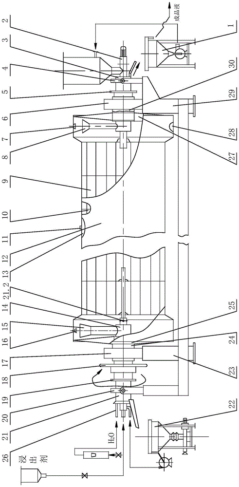
The invention discloses a rotary continuous leaching unit and a continuous countercurrent leaching method. According to the method, mineral aggregate is added from one end of a closed tunnel container with stirring function, and is continuously moved to the other end; and a leaching solution is injected from the other end of the tunnel container and is continuously moved in the opposite direction to the movement direction of the mineral aggregate, thereby achieving the goal of continuous countercurrent leaching. The practical equipment is an aggregate unit composed of a rotary leaching chamber, a head thickening machine, a tail thickening machine and a matched system. The method and unit disclosed by the invention are used instead of the traditional technique and equipment based on heap leaching, tank leaching, multistage countercurrent vat leaching or the like, thereby implementing continuous high-efficiency operation, simplifying the equipment configuration, adapting to multiple different grades of mineral aggregate, and achieving the goals of energy and manpower saving and environment friendliness.

Description

technical field [0001] The invention relates to the technical field of hydrometallurgy industry, in particular to a rotary continuous leaching unit and a continuous countercurrent leaching method. Background technique [0002] According to the difference in the properties of mineral materials, the extraction methods and equipment of non-ferrous metals are different, and are usually divided into two categories: "fire method" and "wet method". With the development of human economic activities and the enhancement of awareness of environmental protection, the proportion of traditional pyrometallurgy is decreasing year by year. Due to the advantages of high comprehensive recovery rate, low investment and easy control of the environment, hydrometallurgy has made great progress in recent decades. [0003] The leaching process is an important process in the hydrometallurgical process. At present, most of the existing leaching methods are as follows: the mixture in the extractor is...

Claims


Application Information

Patent Timeline
Patent Type & Authority Patents(China)
IPC IPC(8): C22B3/02C22B3/04
CPCY02P10/20
Inventor 薛平魏明星
Owner 薛平
Learn More