Broadband circularly polarized micostrip antenna

A technology of microstrip antenna and circular polarization, which is applied in the direction of antenna, slot antenna, antenna grounding device, etc., can solve the problems of small impedance bandwidth, insufficient frequency band, and narrow axial ratio bandwidth of microstrip antenna, so as to overcome the decrease of antenna gain , Reduce the coverage area and reduce the size of the antenna

Active Publication Date: 2015-06-10
XIDIAN UNIV
View PDF5 Cites 13 Cited by
  • Summary
  • Abstract
  • Description
  • Claims
  • Application Information

AI Technical Summary

Problems solved by technology

Chinese patent authorization number CN 203503788 U discloses a microstrip antenna, its structure is as follows figure 1 As shown, the front of the dielectric material board is printed with a square radiating patch with cut corners, and any side of the radiating patch is provided with a slot that extends deeply toward the other opposite side, and the two slots on the same pair of opposite sides The length of the slots is less than half of the vertical distance of the pair of sides, and they are parallel to each other and staggered from each other. The four slots are in a centrally symmetrical relationship with respect to the geometric center of the radiation patch, and the coaxial line passes through the radiation unit and the opening on the radiation floor. Feed, the antenna can achieve miniaturization and wide frequency band, but its frequency band is still not wide enough
[0005] Due to the shortcomings of the traditional microstrip antenna's small impedance bandwidth and narrow axial ratio bandwidth, the application range of the antenna is limited, making it impossible to use on multiple platforms, nor can it be used in multiple frequency bands on one platform
The simple and effective way to increase the bandwidth is to increase the thickness of the medium and reduce the relative permittivity value of the substrate, but the excessive thickness of the medium will cause obvious excitation of surface waves and may excite some high-order modes in the thickness direction, which will reduce the radiation efficiency, worsens the radiation pattern and poses some problems for the feed
Reducing the relative permittivity of the substrate can reduce surface waves, but the potential for this improvement is limited, and its minimum value ε r = 1, that is, use air medium

Method used


Image

  • Broadband circularly polarized micostrip antenna
  • Broadband circularly polarized micostrip antenna
  • Broadband circularly polarized micostrip antenna

Examples


Embodiment 1

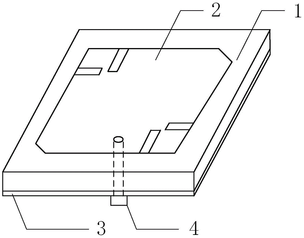
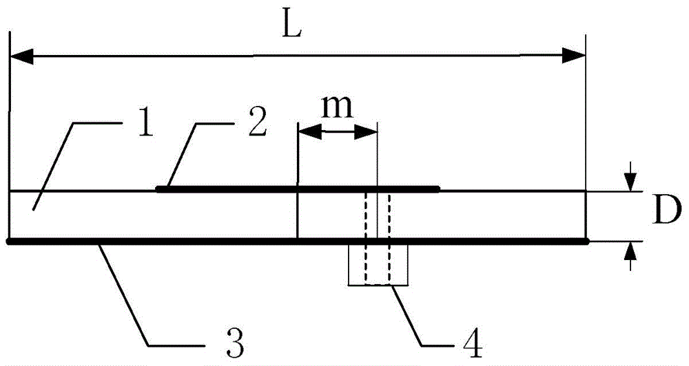
[0032] refer to figure 2 , the radiating unit 2 with cut corners and the radiating floor 3 are respectively printed on the upper and lower surfaces of the dielectric board 1, the dielectric material board 1 is a square dielectric board with a dielectric constant of 10.92, its side length is L=35.72mm, and its thickness is D=3.18mm. The present invention uses the coaxial line 4 located at the right side of the center of the dielectric plate 1 at m=5mm for power feeding, and the inner core of the coaxial line 4 passes through the threading hole on the dielectric material plate and is welded with the radiating unit 2 with cut corners. The outer skin is welded to the radiant floor 3.

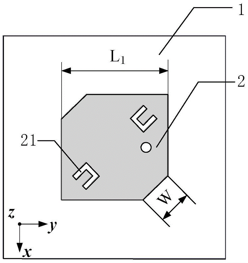
[0033] refer to image 3 , the radiation unit 2 with cut corners is printed on the top of the dielectric board 1, the radiation unit is a square patch with the upper left corner and lower right corner cut off, and the side length of the square patch is L 1 =17mm, length of the chamfered hypotenu...

Embodiment 2

[0038] The structure of embodiment 2 is identical with the structure of embodiment 1, and following parameter has been adjusted:

[0039] The length of the U-shaped groove 21 is W 2 =2.8mm, the distance from the outer side to the center of the radiation unit 2 is W 4 =5.5mm, the diameter of the circular slot is D=4.4mm, and the distance between the center of the circle and the center of the square patch 33 is d 1 = 9 mm.

Embodiment 3

[0040] The structure of embodiment 3 is identical with the structure of embodiment 1, and following parameter has been adjusted:

[0041] The length of the U-shaped groove 21 is W 2 = 3mm, the distance from the outer side to the center of the radiation unit 2 is W 4 =6mm, the diameter of the circular slot is D=4.8mm, and the distance between the center of the circle and the center of the square patch 33 is d 1 = 9.5 mm.

[0042] Effect of the present invention can be further explained in conjunction with simulation result:

[0043] 1. Simulation content

[0044] 1.1 Utilize commercial emulation software HFSS_13.0 to the S of above-mentioned embodiment 1 11 The parameters are simulated and calculated, and the results are as follows Figure 8 shown.

[0045] 1.2 Utilize the commercial simulation software HFSS_13.0 to simulate the axial ratio of the above-mentioned embodiment 1, the results are as follows Figure 9 shown.

[0046] 1.3 Using the commercial simulation softw...


PUM


Abstract

The invention discloses a broadband circularly polarized micostrip antenna. The broadband circularly polarized micostrip antenna is used for solving the problem of narrow working band of existing circularly polarized microstrips. The broadband circularly polarized micostrip antenna comprises a dielectric slab (1), a radiating unit (2), a radiating bottom slab (3) and a coaxial cable (4). The upper surface and the lower surface of the dielectric slab (1) are printed with the radiating unit (2) and the radiating bottom slab (3) respectively; the radiating bottom slab (3) is composed of a square patch (33), eight quasi-fractal units (31) and a metal strip (32), wherein the diagonals of the square patch (33) are symmetrically etched with four composite-structured slots (331) and equal-arm L-type slots (332),the eight quasi-fractal units (31) are uniformly distributed outside the square patch (33) and connected through the metal strip (32); along the diagonal without truncated angles of the square patch, the radiating unit (2) is symmetrically etched with two U-type slots (21) with outward openings. The broadband circularly polarized microstrip antenna has the advantages of being broad in band and small in size and can be applied to radio frequency identification, radar and wireless communication.

Description

technical field [0001] The invention belongs to the technical field of antennas, and relates to a broadband circularly polarized microstrip antenna, which can be used for radio frequency identification, radar and wireless communication to receive and transmit circularly polarized electromagnetic waves within a wide frequency band. Background technique [0002] According to the polarization characteristics, antennas can be divided into three types: linear polarization, circular polarization and elliptical polarization. The bandwidth refers to the main performance parameters of the antenna in the frequency range that can meet the design index requirements, such as input impedance, pattern, gain , main lobe width and side lobe level, etc. In general, antenna performance parameters vary with frequency, so the antenna bandwidth depends on the frequency characteristics of each performance parameter. For circularly polarized antennas, their polarization characteristics are often th...

Claims


Application Information

Patent Timeline
Patent Type & Authority Applications(China)
IPC IPC(8): H01Q13/08H01Q13/10H01Q1/36H01Q1/38H01Q1/48H01Q1/50
Inventor 任俊毅龚书喜姜文张坤哲洪涛
Owner XIDIAN UNIV
Why Eureka
Try Eureka