A dry distillation device for solid heat carrier and its dry distillation method

A technology of solid heat carrier and dry distillation, which is applied in the direction of direct heating dry distillation, special form dry distillation, petroleum industry, etc. It can solve the problems of increasing the difficulty of gas-solid separation, fine particle size of semi-coke products, and large amount of dust, so as to shorten the high temperature residence time , little mechanical wear and no power consumption

Active Publication Date: 2017-03-22
QUJING ZHONGYI FINE CHEMICAL INDUSTRY CO LTD
View PDF7 Cites 0 Cited by
  • Summary
  • Abstract
  • Description
  • Claims
  • Application Information

AI Technical Summary

Problems solved by technology

In addition, whether it is fluidized bed, entrained bed dry distillation, or solid heat carrier moving bed dry distillation, they all belong to the "isothermal" dry distillation process, and the moisture and volatile matter escape instantly, which can easily cause thermal collapse, making the particle size of semi-coke products smaller. Fine, the amount of dust is larger, which increases the difficulty of gas-solid separation

Method used


Image

  • A dry distillation device for solid heat carrier and its dry distillation method
  • A dry distillation device for solid heat carrier and its dry distillation method
  • A dry distillation device for solid heat carrier and its dry distillation method

Examples


Embodiment 1

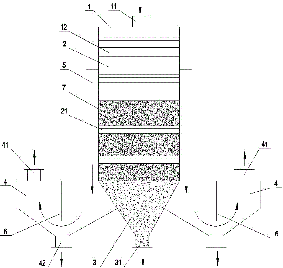
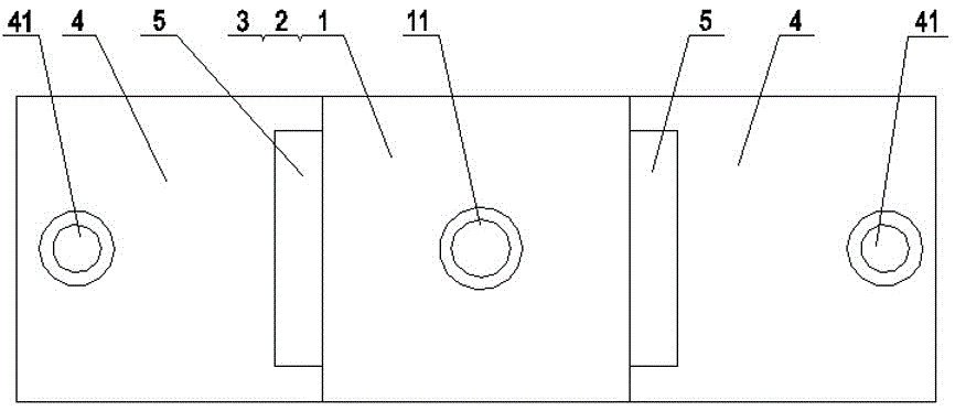
[0037] Such as figure 1 , 2 As shown in and 3, the dry distillation material is lignite particles with a particle size of 5-6mm accounting for 94% and the solid heat carrier is granular hot semi-coke.

[0038] A. The above-mentioned lignite grains and hot semi-coke are fed together from the feeding port on the upper part of the mixing chamber, mixed from top to bottom through the staggered "Λ" shaped triangular mixing plates, and then fall into the carbonization chamber to form a material layer;

[0039] B. The lignite particles in the material layer release volatile matter through pyrolysis of the heated semi-coke in the retort chamber, and the volatile matter passes through the material layer upwards and enters the "Λ"-shaped angular boxes arranged in dislocation from top to bottom, and passes through it The outlet hole is exported, and the dry distillation solid product formed after dry distillation falls down into the dry distillation solid product chamber and is discharg...

Embodiment 2

[0042] The retort material is oil shale particles with a particle size of 13-15mm, accounting for 97%, and the solid heat carrier is hot semi-coke.

[0043] A. The above-mentioned oil shale particles and hot semi-coke are put in together from the feeding port on the upper part of the mixing chamber, mixed from top to bottom through the staggered "Λ" shaped triangular mixing plates, and then fall into the carbonization chamber to form a material layer;

[0044] B. The oil shale particles in the material layer release volatile matter through hot semi-coke heating and pyrolysis in the retort chamber, and the volatile matter passes through the material layer upwards and enters the "Λ" shape arranged in dislocation from top to bottom plus the lower two side baffles In the angular box of plate structure, it is exported through the outlet hole, and the dry distillation solid product formed after dry distillation falls down into the dry distillation solid product chamber and is dischar...

Embodiment 3

[0047] The dry distillation material is lignite particles with a particle size of 8-10mm, accounting for 88%, and the solid heat carrier is hot ash.

[0048] A. Put the above-mentioned lignite particles and hot ash together from the feeding port on the upper part of the mixing chamber, mix them through the staggered "Λ" triangular mixing plates from top to bottom, and then fall into the retort chamber to form a material layer;

[0049] B. The lignite particles in the material layer are heated and pyrolyzed by the hot ash in the retort chamber to release volatile matter, and the volatile matter passes through the material layer upwards and enters the "Λ" shape with baffles on both sides of the lower part arranged in dislocation from top to bottom. In the angular box, it is exported through the outlet hole therein, and the dry distillation solid product formed after dry distillation falls down into the dry distillation solid product chamber and is discharged through the discharge...


PUM

PropertyMeasurementUnit
particle sizeaaaaaaaaaa

Abstract

The invention discloses a destructive distillation device and a destructive distillation method of a solid heat carrier. A mixing chamber of the destructive distillation device is provided with a feed opening, triangular baffling and mixing plates are arranged in the mixing chamber in a stagger manner, multiple layers of angular boxes are arranged in a destructive distillation chamber, derivation holes are formed in the angular boxes and are communicated with a settling chamber through volatile matter channels, a discharge opening is formed in the lower part of a destructive distillation solid product chamber, an oil gas outlet is formed in the upper part away from a volatile matter channel interface of the settling chamber, and a dust outlet is formed in the bottom of the settling chamber. The destructive distillation method comprises: a destructive distillation raw material and the solid heat carrier enter the mixing chamber from the feed opening and drop into the destructive distillation chamber to form a material layer after being mixed by the triangular baffling and mixing plates, the destructive distillation raw material is heated in the destructive distillation chamber to pyrolyze to release a volatile matter, the volatile matter enters the angular boxes and enters the settling chamber through the derivation holes and the volatile matter channels, a destructive distillation solid product is discharged from the discharge opening, the volatile matter enters the settling chamber, and a gas and a solid are separated and are respectively discharged from the oil gas outlet and the dust outlet. The destructive distillation device and destructive distillation method of solid heat carrier disclosed by the invention have the advantages of low power consumption, little equipment wear, good gas-solid separation effect and high resource utilization rate.

Description

technical field [0001] The invention belongs to the technical field of energy and chemical engineering, and in particular relates to a solid heat carrier dry distillation device and a dry distillation method with low power consumption, small equipment wear, good gas-solid separation effect and high resource utilization rate. Background technique [0002] my country is rich in coal resources. Except for some of the raw coal used for coking and conversion processing, most of it is used for direct combustion, which not only has low thermal efficiency and serious damage to the environment, but also the hydrogen-rich components with high economic value in coal cannot be obtained. Reasonable use. Moreover, my country's oil shale and oil sand reserves are abundant, and the potential for resource development is huge. [0003] At present, most of the coal or oil shale low-temperature carbonization technology adopts block gas heat carrier carbonization technology. For example, the low...

Claims


Application Information

Patent Timeline
Patent Type & Authority Patents(China)
IPC IPC(8): C10B53/04C10B53/06C10B49/16C10G1/00
CPCC10B49/16C10B53/04C10B53/06
Inventor 刘长胜罗国林
Owner QUJING ZHONGYI FINE CHEMICAL INDUSTRY CO LTD
Why Eureka
Try Eureka