Method for doping distribution of solar cell emitter

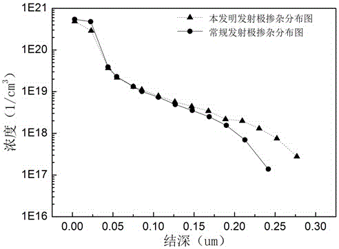
A solar cell and doping distribution technology, applied in circuits, photovoltaic power generation, electrical components, etc., can solve problems such as uneven doping concentration distribution of silicon wafers, low conversion efficiency of crystalline silicon solar cells, and reduced short-wave response of cells, etc., to achieve Improve short-wave response, improve conversion efficiency, and improve the effect of junction depth

Active Publication Date: 2016-10-05
CECEP SOLAR ENERGY TECH (ZHENJIANG) CO LTD
View PDF4 Cites 0 Cited by
  • Summary
  • Abstract
  • Description
  • Claims
  • Application Information

AI Technical Summary

Problems solved by technology

[0004] The conventional emitter doping distribution is formed by one-time power-on and one-time push-in process, so it has a higher surface doping concentration, so the "dead layer" is thicker, which greatly reduces the short-wave response of the battery, and the doping in the silicon wafer The low impurity concentration makes the distribution of doping concentration on the surface and body of the silicon wafer uneven, resulting in poor diffusion uniformity, so the conversion efficiency of crystalline silicon solar cells is low

Method used


Image

  • Method for doping distribution of solar cell emitter
  • Method for doping distribution of solar cell emitter

Examples


Embodiment 1

[0019] Embodiment 1: A method for doping distribution of a solar cell emitter, the process steps are as follows:

[0020] (1) Entering the boat: Insert the silicon wafer after texturing into the quartz boat and enter the diffusion furnace. The time for entering the boat is 8 minutes; the initial temperature of the diffusion furnace is 750°C. Into large nitrogen;

[0021] (2), heating up: the temperature of the diffusion furnace is raised to 810° C., and the heating time is 15 minutes. During the heating process, the diffusion furnace keeps feeding large amounts of nitrogen;

[0022] (3) Pre-oxidation: maintain the temperature of the diffusion furnace at 810° C., feed nitrogen and oxygen into the diffusion furnace to pre-oxidize the surface of the silicon wafer, and the oxidation time is 10 minutes. Oxygen volume percentage is 10%;

[0023] (4) The first source diffusion: maintain the temperature of the diffusion furnace at 810°C, feed large nitrogen, oxygen, and small nitrog...

Embodiment 2

[0032] Embodiment 2: roughly the same as Example 1, the difference is that the volume percentage of oxygen is 7% during the pre-oxidation, and the volume percentage of the small nitrogen carrying phosphorus source is 17% during the first source diffusion, and the second time source diffusion The volume percentage of phosphorus-carrying source nitrogen is 12%.

Embodiment 3

[0033] Embodiment 3: roughly the same as Example 1, the difference is that the volume percentage of oxygen is 11% during the pre-oxidation, and the volume percentage of nitrogen carrying phosphorus source is 18% during the first source diffusion, and the second time source diffusion The volume percentage of phosphorus-carrying source nitrogen is 13%.


PUM


Abstract

The invention discloses a solar cell emitter doping distribution method. The solar cell emitter doping distribution method includes the steps of pre-oxidation, two times of source communication diffusion and two times of junction pushing for cooling and boat discharging. solar cell emitter doping distribution is realized through multiple times of source communication and multiple times of junction pushing, the time, temperature and source communication amount of multiple times of diffusion and the time and temperature of multiple times of junction pushing are adjusted, a solar cell emitter is made to have a lower surface doping concentration, and therefore the influences of a 'dead layer' are obviously weakened, and the short wave response of a solar cell is improved. The process of multiple times of source communication and multiple times of junction pushing further improves the doping concentration in a silicon wafer body, the silicon wafer surface doping concentration and the doping concentration inside the silicon wafer body are uniform, diffusion uniformity is good, and therefore the diffusion sheet resistance uniformity is improved. The process of multiple times of junction pushing improves the junction depth and increases blue light response of the solar cell, and finally the purpose of improving the conversion efficiency of the crystalline silicon solar cell is realized.

Description

technical field [0001] The invention relates to the field of preparation of crystalline silicon solar cells, in particular to an emitter doping distribution method. Background technique [0002] In the 21st century, human beings will face the great challenge of achieving sustainable economic and social development. With the increasing global energy shortage and environmental pollution, the task of developing and utilizing new alternative energy becomes very urgent. Therefore, as a clean and inexhaustible new energy source, solar cells have the advantages of safety and environmental friendliness. It can effectively alleviate the energy shortage problem without polluting the environment, which meets the requirements of the national sustainable development strategy. [0003] In the structure of crystalline silicon solar cells, the emitter is the core part that forms the p-n junction. After the p-n junction is formed, an electric field can be generated in the silicon wafer. When...

Claims


Application Information

Patent Timeline
Patent Type & Authority Patents(China)
IPC IPC(8): H01L31/18
CPCH01L31/022425H01L31/18Y02E10/50Y02P70/50
Inventor 黄惜惜黄青松范维涛勾宪芳黄钧林
Owner CECEP SOLAR ENERGY TECH (ZHENJIANG) CO LTD
Why Eureka
Try Eureka