High-temperature-resistant high-bonding-strength low infrared emissivity composite coating, metal alloy material with coating and preparation method of metal alloy material

A low-infrared emission and composite coating technology, which is applied in the coating, overlay coating, metal material coating process, etc., can solve the problems of coating performance deterioration, high equipment requirements, high cost, etc., and achieve high temperature stability Effects of improved emissivity, excellent bonding strength, and increased operating temperature

Active Publication Date: 2015-08-05
NAT UNIV OF DEFENSE TECH
View PDF5 Cites 23 Cited by
  • Summary
  • Abstract
  • Description
  • Claims
  • Application Information

AI Technical Summary

Problems solved by technology

The low-emissivity coating of the organic system is not used at a high temperature, and the service temperature generally does not exceed 400°C, so it is not suitable for use in the harsh environment of high-speed aircraft
The low-emissivity coatings of inorganic systems have a relatively high temperature range, and their temperature resistance can even exceed 1000°C. However, most of the low-emissivity coatings of inorganic systems are not ideal for use in high-temperature environments.
The main reasons for the above problems are: first, most low-emissivity fillers are unstable in high-temperature environments and are prone to migration; second, the metal or alloy materials used in aircraft are easy to diffuse to the infrared coa

Method used


Image

  • High-temperature-resistant high-bonding-strength low infrared emissivity composite coating, metal alloy material with coating and preparation method of metal alloy material
  • High-temperature-resistant high-bonding-strength low infrared emissivity composite coating, metal alloy material with coating and preparation method of metal alloy material
  • High-temperature-resistant high-bonding-strength low infrared emissivity composite coating, metal alloy material with coating and preparation method of metal alloy material

Examples


Embodiment 1

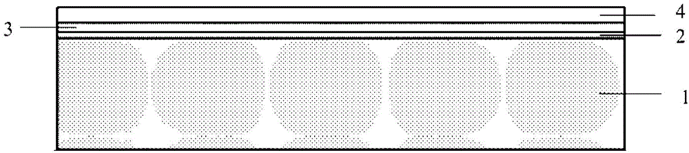
[0044] Such as figure 1 Shown, a kind of metal alloy material that is coated with the low infrared emissivity composite coating of high temperature resistance, high bonding strength of the present invention, comprises metal alloy substrate 1 (metal alloy substrate adopts aerospace K424 alloy) and is coated on metal A low-infrared emissivity composite coating on the alloy substrate 1, the low-infrared emissivity composite coating is a multi-layer superposition structure, and the multi-layer superposition structure includes a metal bonding layer 2, a ceramic transition layer 3 and a low emissivity function from the inside to the outside. Layer 4, wherein the metal bonding layer 2 is a NiCrAlY plasma sprayed layer, and the ceramic transition layer 3 is ZrO 2 Plasma sprayed layer, low emissivity functional layer 4 is ZrO containing AgPd alloy 2 -Al 2 o 3 -SiO 2 Department of glass coating. The thickness of the metal bonding layer 2 is controlled to be 100 μm, the thickness of...

Embodiment 2

[0058] Such as figure 1 Shown, a kind of metal alloy material that is coated with high temperature resistance of the present invention, the low infrared emissivity composite coating of high binding strength comprises metal alloy substrate 1 (metal alloy substrate adopts 1Cr17 stainless steel substrate) and is coated on metal alloy A low-infrared-emissivity composite coating on the substrate 1, the low-infrared-emissivity composite coating is a multi-layer superposition structure, and the multi-layer superposition structure sequentially includes a metal bonding layer 2, a ceramic transition layer 3 and a low-emissivity functional layer from the inside to the outside 4. Among them, the metal bonding layer 2 is NiCrAlY plasma sprayed layer, and the ceramic transition layer 3 is ZrO 2 Plasma sprayed layer, low emissivity functional layer 4 is ZrO containing AgPd alloy 2 -Al 2 o 3 -SiO 2 Department of glass coating. The thickness of the metal bonding layer 2 is controlled to b...

Embodiment 3

[0072] Such as figure 1 Shown, a kind of metal alloy material that is coated with the low infrared emissivity composite coating of high temperature resistance, high bonding strength of the present invention, comprises metal alloy substrate 1 (metal alloy substrate adopts 304 alloy steel) and is coated on metal alloy substrate A low-infrared-emissivity composite coating on 1, the low-infrared-emissivity composite coating is a multi-layer superposition structure, and the multi-layer superposition structure sequentially includes a metal bonding layer 2, a ceramic transition layer 3 and a low-emissivity functional layer 4 from the inside to the outside , where the metal bonding layer 2 is NiCrAlY plasma sprayed coating, and the ceramic transition layer 3 is ZrO 2 Plasma sprayed layer, low emissivity functional layer 4 is ZrO containing AgPd alloy 2 -Al 2 o 3 -SiO 2 Department of glass coating. The thickness of the metal bonding layer 2 is controlled to be 150 μm, the thicknes...


PUM

PropertyMeasurementUnit
Thicknessaaaaaaaaaa
Thicknessaaaaaaaaaa
Surface roughnessaaaaaaaaaa

Abstract

The invention discloses a high-temperature-resistant high-bonding-strength low infrared emissivity composite coating which sequentially comprises a NiCrAlY plasma spraying layer, a ZrO2 plasma spraying layer and ZrO2-Al2O3-SiO2 system containing AgPd alloy glass coating from inside to outside. The surface roughness of a metal alloy material coated with the coating is lower than 2.0 micrometers, the bonding strength of the metal alloy material exceeds 10MPa, the tolerable temperature of the coating is higher than 1000 DEG C, and the average infrared emissivity of the coating in a specified band is less than 0.3. A preparation method of the metal alloy material includes the steps: firstly, performing sand blasting for a base; secondly, sequentially spraying the NiCrAlY layer and the ZrO2 layer on the base by a plasma spraying process; finally, uniformly brushing or printing coatings on the ZrO2 layer, and drying and sintering the coatings to obtain the finished metal alloy material. The metal alloy material can be used in a high-temperature environment, infrared radiation of a high-temperature component is effectively reduced, and the metal alloy material is stable in performance and low in cost.

Description

technical field [0001] The invention relates to the technical field of functional coatings and composite materials thereof, in particular to a composite coating with low infrared emissivity, a metal alloy material and a preparation method thereof. Background technique [0002] The infrared detector collects the infrared signals of the target in the bands of 3 μm to 5 μm (high temperature) and 8 μm to 14 μm (normal temperature), and then uses the difference in infrared radiation energy between the target and the background to identify the target through imaging. According to the calculation formula of infrared radiation energy difference: △W=σε 目 T 目 4 -σε 背 T 背 4 , where, ε 目 is the infrared emissivity of the target, ε 背 is the infrared emissivity of the background, T 目 is the surface temperature of the target, T 背 is the background temperature. Usually, the surface temperature of the target will be higher than that of the background due to heat generation, etc. 目...

Claims


Application Information

Patent Timeline
IPC IPC(8): C23C28/00C23C4/10C23C4/08
Inventor 刘海韬程海峰田浩黄文质周永江
Owner NAT UNIV OF DEFENSE TECH
Why Eureka
Try Eureka