Piezoelectric type two-block cascaded micro mechanical filter

A piezoelectric and micro-mechanical technology, applied in the direction of electrical components, impedance networks, etc., can solve the problem that the adjustment of the center frequency and bandwidth of the filter is not very flexible, there are few types of piezoelectric filters, and the bandwidth of piezoelectric filters is narrow and other problems, to achieve the effect of sharp cut-off performance, simple and compact overall structure, and high Q value

Inactive Publication Date: 2015-08-05
UNIV OF ELECTRONICS SCI & TECH OF CHINA
View PDF5 Cites 5 Cited by
  • Summary
  • Abstract
  • Description
  • Claims
  • Application Information

AI Technical Summary

Problems solved by technology

Therefore, due to the capacitive structure of the capacitive filter, its structure is more complicated than that of the piezoelectric filter, and the processing process is more complicated and difficult.
At the same time, capacitive filters must be loaded with a DC bias to work, and the efficiency of energy conversion is lower than that of piezoelectric filters.
At present, the research on piezoelectric filters is not particularly mature. The types of piezoelectric filters that have been studied are relatively small, and the bandwidth of piezoelectric filters is relatively narrow. For the adjustment of the center frequency and bandwidth of the filter are not very flexible

Method used


Image

  • Piezoelectric type two-block cascaded micro mechanical filter
  • Piezoelectric type two-block cascaded micro mechanical filter
  • Piezoelectric type two-block cascaded micro mechanical filter

Examples


Embodiment Construction

[0020] The present invention will be described in further detail below in conjunction with specific embodiments and accompanying drawings.

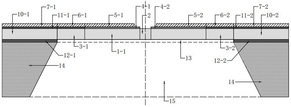
[0021] In this embodiment, an SOI substrate is used to make a filter, and the SOI substrate is composed of a thick polysilicon substrate, a 1 μm silicon dioxide insulating layer and a 10 μm single crystal silicon structure layer.

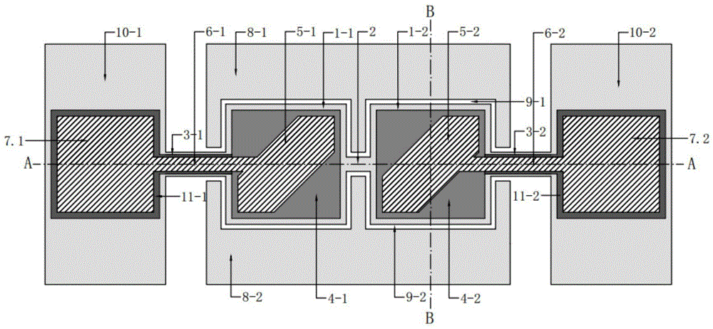
[0022] The structure of the piezoelectric two-block cascaded micromechanical filter is as follows: figure 1 As shown, when the filter is made:

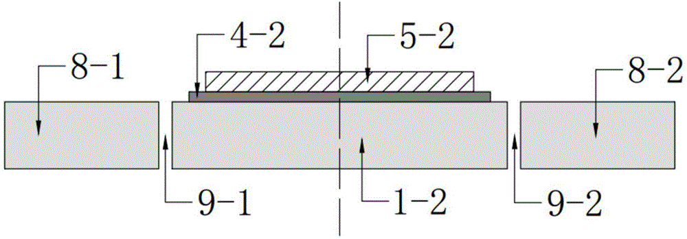
[0023] First grow a layer of silicon dioxide insulating layer on the single crystal silicon of the SOI substrate, apply photoresist photolithography, and use reactive ion etching to obtain silicon dioxide layers 11-1, 11 covering the support beams and support platforms -2; then use reactive sputtering to obtain a piezoelectric film, and then use wet etching to obtain piezoelectric film layers 4-1 and 4-2 covering the vibration block;

[0024] Reactive sputtering is t...


PUM


Abstract

The invention belongs to the original device technical field in the radio frequency communication and micro electro mechanical system (MEMS) technical field and provides a piezoelectric type two-block cascaded micro mechanical filter. The piezoelectric type two-block cascaded micro mechanical filter includes two vibration blocks with the same size, a coupling beam, supporting beams, supporting stages, an input electrode, an output electrode, direct current bias electrodes, piezoelectric film layers and an insulating substrate; the two vibration blocks are connected with each other through the coupling beam; the two vibration blocks are also connected with the supporting stages through the supporting beams which are fixed at the middle point of one side edge of each vibration block respectively; the two vibration blocks are arranged on the insulating substrate in a suspension manner; the vibration blocks are covered with one piezoelectric film respectively; the input electrode and the output electrode are arranged on the piezoelectric films respectively; one pair of direct current bias electrodes surround the two vibration blocks; and the direct current bias electrodes and the vibration blocks form a capacitance structure. According to the piezoelectric type two-block cascaded micro mechanical filter of the invention, a piezoelectric structure is adopted, and the filter can be formed through the coupling of the two vibration blocks, and therefore, the piezoelectric type two-block cascaded micro mechanical filter has the advantages of simple and compact structure, reduced processing difficulty, high coupling efficiency, high Q value and better sharp cut-off.

Description

technical field [0001] The invention belongs to the technical field of components in the technical field of radio frequency communication and micro-electromechanical systems (MEMS), and in particular relates to a micro-mechanical filter formed by coupling two completely identical piezoelectric micro-mechanical resonators. Background technique [0002] With the further requirements of high performance and miniaturization of electronic equipment, electronic components are developing in the direction of high performance, low cost and low power consumption. High Q value, miniaturized resonators and filters become the bottleneck of on-chip and miniaturized electronic communication systems in the future. The RF MEMS filter is a high-performance RF filter device based on mechanical vibration made using MEMS technology. The input electrical signal is converted into mechanical vibration through electromechanical coupling. The filtering function is completed in the mechanical domain, ...

Claims


Application Information

Patent Timeline
Patent Type & Authority Applications(China)
IPC IPC(8): H03H9/19
Inventor 鲍景富李昕熠陈兆隽黄裕霖秦风安佳琪张翼
Owner UNIV OF ELECTRONICS SCI & TECH OF CHINA
Why Eureka
Try Eureka