Quartz pitchfork type laser breakdown detection device

A quartz tuning fork and laser breakdown technology, which is applied in the field of spectrum measurement, can solve the problems of indistinguishable spectral lines, decreased detection sensitivity, and low detection sensitivity, and achieve the effects of increasing the detection limit, improving the detection sensitivity, and simplifying the detection system

Active Publication Date: 2015-08-12
NANJING INST OF ADVANCED LASER TECH
View PDF6 Cites 6 Cited by
  • Summary
  • Abstract
  • Description
  • Claims
  • Application Information

AI Technical Summary

Problems solved by technology

[0004] At present, the detection limit of the current laser-induced breakdown spectroscopy is on the order of ppm, and there is still a problem of low detection sensitivity.
However, when using pho

Method used


Image

  • Quartz pitchfork type laser breakdown detection device
  • Quartz pitchfork type laser breakdown detection device
  • Quartz pitchfork type laser breakdown detection device

Examples


Embodiment 1

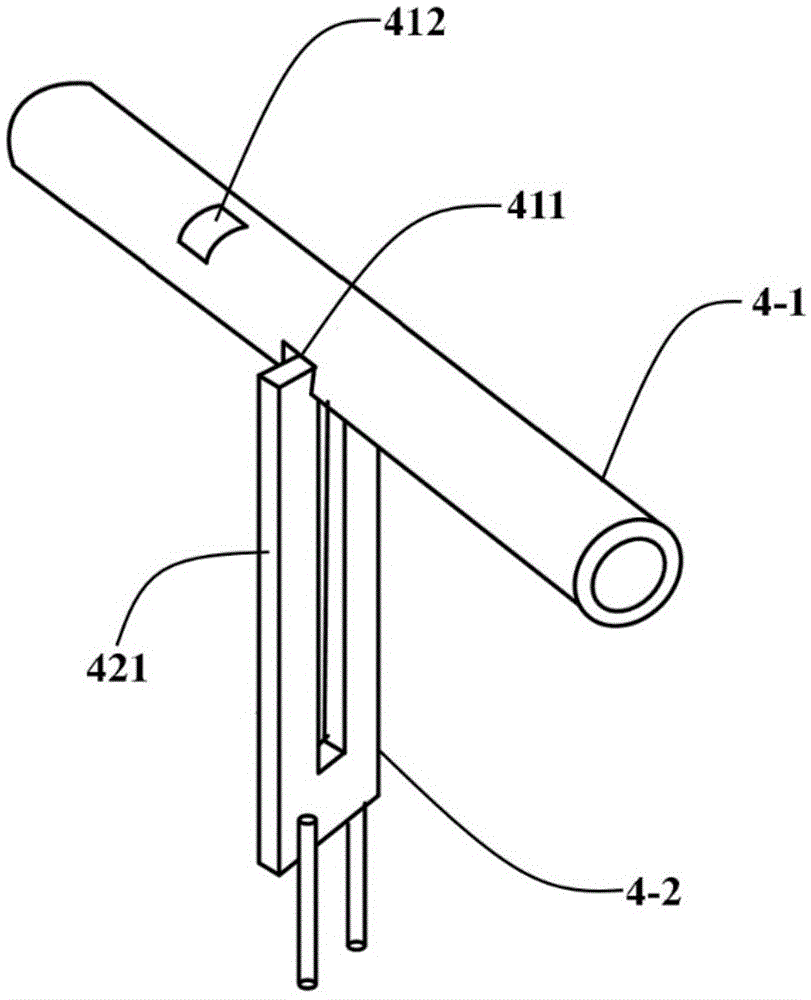
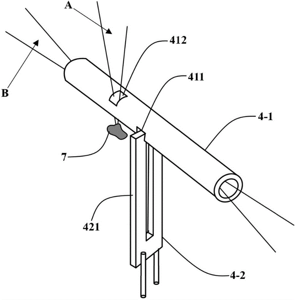
[0028] figure 1 , figure 2 Shown is the structure and working state of the quartz tuning fork detector of the present invention, mainly by resonant tube 4-1 and quartz tuning fork 4-2, quartz tuning fork 4-2 has two vibrating arms 421, the plane of vibrating arm 421 and resonant tube 4-2 1. The axes are parallel, and the two vibrating arms 421 will generate reciprocating vibration after the quartz tuning fork 4-2 is externally excited. The lower part of the quartz tuning fork 4-2 has two electrodes, one is connected to the signal ground, and the other is used to output the electric signal generated by the vibration. The two vibrating arms 421 of the quartz tuning fork 4-2 are located at an open groove 411 at the bottom of the resonance tube 4-1. The axis of the resonance tube 4-1 is coaxial with the optical path of the detection light B. When the detection light B passes through the resonance tube 4-1, it is The substance to be measured 7 absorbs, and the sound energy is re...

Embodiment 2

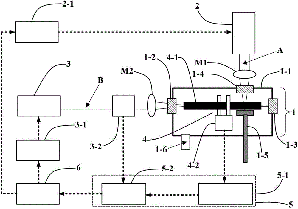
[0041] Such as Figure 4 Shown is the structure of the detection device with different modulation methods. Wherein the detection light source 3 is a semiconductor laser, its input end is connected with the detection light source controller 3-1, and the detection light source controller 3-1 is connected with the function generator 3-3 and the host computer 6 respectively, and the host computer 6 passes through the detection light source controller 3-1. 1 Realize the switching control of the detection light source 3, and at the same time, the function generator 3-3 provides a modulation signal to the detection light source 3 through the detection light source controller 3-1, and the modulation frequency is f 0 Integer multiple of / 2; host 6 is connected with lock-in amplifier 5-2, lock-in amplifier 5-2 is connected with function generator 3-3 and preamplifier 5-1, preamplifier 5-1 is connected with quartz tuning fork 4- 2 outputs are connected. All the other structures are the...


PUM

PropertyMeasurementUnit
Lengthaaaaaaaaaa
Outer diameteraaaaaaaaaa
Inner diameteraaaaaaaaaa

Abstract

A quartz pitchfork type laser breakdown detection device comprises an optoacoustic absorption chamber, an excitation light source, a detection light source, a detection light modulation unit, a quartz pitchfork detector and the like. The quartz pitchfork detector comprises a resonating tube and a quartz pitchfork. During working, excitation light is focused and emitted to a to-be-detected substance, the to-be-detected substance generates a nano particle cloud cluster due to heating, the nano particle cloud cluster is diffused into the optoacoustic absorption chamber, detection light is absorbed by elements of the nano particle cloud cluster to generate an optoacoustic effect, acoustic energy accumulates in the resonating tube and is transmitted to the quartz pitchfork to output an electric signal, and accordingly, the content of a certain element in the to-be-detected substance is calculated. The quartz pitchfork type laser breakdown detection device has the advantages that laser induce breakdown and optoacoustic spectroscopy are combined, and detection limits of conventional laser induce breakdown methods are increased; the quartz pitchfork serves as the detector, and a detection system is simplified effectively; the optoacoustic absorption chamber is vacuumized, spectral line widening effect is low, detected spectral lines are easy to distinguish and low in noise, and accordingly, detection sensitivity is improved.

Description

technical field [0001] The invention relates to the technical field of spectrum measurement, in particular to a laser-induced breakdown detection device using quartz tuning fork photoacoustic spectroscopy, which is suitable for quantitative analysis of substance concentration. Background technique [0002] Laser-induced breakdown spectroscopy is a laser ablation spectral analysis method. The laser is focused on the substance to be measured (which can be solid, liquid or gas) through a lens. When the energy density of the laser is greater than the breakdown threshold of the substance to be measured, the first Nanoscale cloud clusters will be generated, and plasma will be generated if the laser continues to irradiate. The local energy density and temperature of this plasma are very high. Use a spectrometer to collect the signal of the emission line generated on the plasma surface of the substance to be measured, and then you can use the emission Quantitatively analyze the conc...

Claims


Application Information

Patent Timeline
IPC IPC(8): G01N21/63
Inventor 王欢陈昱李建春
Owner NANJING INST OF ADVANCED LASER TECH
Why Eureka
Try Eureka