CO2 electrochemical reduction method with Ag-containing electrode as working electrode

A working electrode, electrochemical technology, applied in the direction of electrodes, electrolysis process, electrolysis components, etc., can solve the problems of low reduction current density, low reduction product amount, low Faradaic efficiency, etc., to suppress side reactions, improve product efficiency, prevent negative effect

Active Publication Date: 2015-08-19
HARBIN INST OF TECH
View PDF5 Cites 28 Cited by
  • Summary
  • Abstract
  • Description
  • Claims
  • Application Information

AI Technical Summary

Problems solved by technology

[0004] The purpose of the invention is to solve the existing CO 2 The electrochemical reduction method has the problems of low redu

Method used


Image

  • CO2 electrochemical reduction method with Ag-containing electrode as working electrode
  • CO2 electrochemical reduction method with Ag-containing electrode as working electrode
  • CO2 electrochemical reduction method with Ag-containing electrode as working electrode

Examples


specific Embodiment approach 1

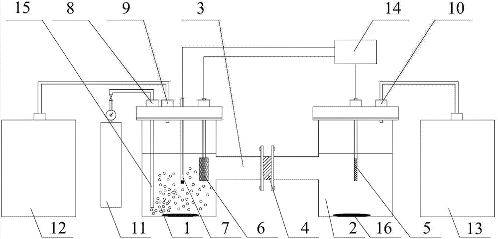
[0015] Specific implementation mode 1: This implementation mode is a CO with an Ag-containing electrode as the working electrode. 2 The electrochemical reduction method is specifically completed according to the following steps: 1. Configure the electrolyte: mix the ionic liquid and ultrapure water to obtain an electrolyte, and the molar fraction of the ionic liquid in the electrolyte is 40%; 2. Equipment assembly: The electrolytic cell of the three-electrode system is arranged in an H shape, that is, the electrolytic cell is divided into an anode pool and a cathode pool, and the anode pool and the cathode pool are connected by a channel. Separated from the anode pool, pour the electrolyte solution into the electrolytic cell of the three-electrode system until the channel between the anode pool and the cathode pool is filled with electrolyte solution, use the platinum sheet as the counter electrode, and place the counter electrode in the three-electrode system. In the anode ar...

specific Embodiment approach 2

[0017] Specific embodiment two: the difference between this embodiment and specific embodiment one is: the ionic liquid described in step one is BMIM-BF 4 、EMIM-BF 4 、EMIM-NTF 2 , EMIM-DCA, EMIM-EtSO 4 or EMIM-OAC. Others are the same as the first embodiment.

specific Embodiment approach 3

[0018] Embodiment 3: The difference between this embodiment and Embodiment 1 or 2 is that the Ag-containing electrode described in step 2 is an Ag sheet, a porous Ag sheet, an Ag sheet with an AgO oxide film on the surface, or an Ag particle electrode. Or an Ag particle electrode with an AgO film on the surface. Others are the same as those in Embodiment 1 or 2.


PUM

PropertyMeasurementUnit
Particle sizeaaaaaaaaaa

Abstract

The invention provides a CO2 electrochemical reduction method with an Ag-containing electrode as a working electrode and relates to a CO2 electrochemical reduction method. The CO2 electrochemical reduction method with the Ag electrode as the working electrode is used for solving the problem of low product efficiency of the existing CO2 electrochemical reduction method. The method comprises the following steps: 1, mixing an ionic liquid with ultrapure water to obtain an electrolyte; 2, assembling an apparatus; and 3, performing CO2 electrochemical reduction, namely completing the CO2 electrochemical reduction with the Ag-containing electrode as the working electrode. The CO2 electrochemical reduction method has the advantages that 1, the Ag-containing electrode is taken as the working electrode and the reduction performance is stable, 2, the ionic liquid is mixed with the ultrapure water to obtain the electrolyte, and in combination with taking the Ag-containing electrode as the working electrode, the generation of CO is promoted in a cathode region, and therefore, the product efficiency is greatly improved, and 3, a cathode tank is separated from an anode tank by use of an ion exchange membrane, and consequently, oxygen generated in an anode region is prevented from going into the cathode region to produce negative effects on the reduction reaction. The method is mainly applied to CO2 electrochemical reduction.

Description

technical field [0001] The present invention relates to a CO 2 Electrochemical reduction method. Background technique [0002] At present, global warming caused by carbon dioxide has become one of the most concerned environmental issues in the world. The energy structure is in a critical period of transition from high-carbon utilization to low-carbon utilization, and the concept of environmental protection is gradually being accepted by the general public. In order to reduce the carbon dioxide content in the atmosphere, vigorously developing low-carbon technologies and recycling carbon dioxide through various technical means are the most effective methods. Due to the chemical properties of carbon dioxide are stable and not easy to be activated, currently three methods are mainly used: catalytic hydrogenation, catalytic reforming and electrochemical reduction. However, the traditional catalytic hydrogenation and catalytic reforming methods must be carried out under high te...

Claims


Application Information

Patent Timeline
IPC IPC(8): C25B1/00C25B11/08
CPCC25B1/00C25B11/057
Inventor 王志江罗金姜兆华
Owner HARBIN INST OF TECH
Why Eureka
Try Eureka