DC variable frequency fan

A DC frequency conversion and fan technology, which is applied to non-variable-capacity pumps, AC motor control, components of pumping devices for elastic fluids, etc. efficiency, insufficient lightning protection measures of the controller, etc., to achieve the effect of improving fan efficiency, improving system safety performance, and high specific power consumables

Inactive Publication Date: 2015-08-19
徐伯琴
View PDF4 Cites 0 Cited by
  • Summary
  • Abstract
  • Description
  • Claims
  • Application Information

AI Technical Summary

Problems solved by technology

There are certain defects in the existing DC frequency conversion fan system: solar cells generally use polysilicon materials, which mostly come from the head and tail materials of the microelectronics industry, and the metal impurities and micro-defects in them seriously affect the photoelectric conversion efficiency of solar cells; Ineffective lightning protection measures affect the safety performance of the system; the unavoidable inconsistency between the capacity and self-discharge of multiple battery cells affects the life of the battery; the structure of the inverter circuit of the DC variable frequency fan is complex, and the frequency conversion effect is not ideal; The blades of the fan are in a neat and flush shape. When the fan is running normally, the airflow will generate a vortex when it flows through the trailing edge of the blade, which will not only affect the efficiency of the fan, but also generate vibration and noise; etc.

Method used


Image

  • DC variable frequency fan
  • DC variable frequency fan
  • DC variable frequency fan

Examples


Embodiment Construction

[0017] In order to better understand the technical principle and working process of the embodiments of the present invention, the present invention will be further described in detail below in conjunction with the drawings and specific embodiments.

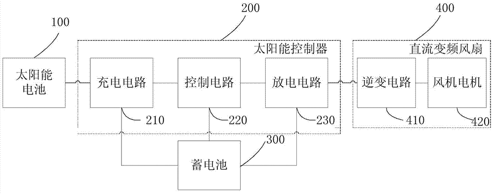
[0018] see figure 1 , shows the functional block diagram of the DC frequency conversion fan system of the present invention. The DC inverter fan system (hereinafter referred to as the system) includes a thin-film solar cell 100, a solar controller 200, a storage battery 300, and a DC inverter fan 400. The solar cell 100 is preferably a thin-film solar cell, and the solar controller 200 has a charging circuit 210 and a discharging circuit 230. And the control circuit 220, the DC variable frequency fan 400 has an inverter circuit 410 and a fan motor 420, the charging circuit 210 is connected between the solar battery 100 and the storage battery 300, the discharge circuit 230 is connected between the storage battery 300 and the inver...


PUM


Abstract

The embodiment of the invention discloses a DC variable frequency fan which is suitable for a DC variable frequency fan system comprising a solar cell, a solar controller, a storage cell and the DC variable frequency fan. The DC variable frequency fan is provided with an inverter circuit and a blower motor. The input end of the inverter circuit is connected with the discharging circuit of the solar controller. The charging circuit of the solar controller is connected between the solar cell and the storage cell. The control circuit of the solar controller is respectively connected with the charging circuit, the discharging circuit and the storage cell. The discharging circuit is also connected with the storage cell. The blower motor is connected with the output end of the inverter motor. The blower motor drives a blower impeller. The blower impeller comprises left and right end plates which are fixed on a rotating shaft. Multiple blades are distributed along the axial direction of the rotating shaft and clamped between the left and right end plates. The cross section edges, which are perpendicular to the rotating shaft, of the blades are longitudinally bent into an arc shape. The DC variable frequency fan system and subsystems are improved so that product performance can be effectively improved, and thus the DC variable frequency fan has advantages of being environment-friendly, economic and convenient to use.

Description

technical field [0001] The invention relates to frequency conversion fan technology, in particular to a DC frequency conversion fan system and its sub-systems. Background technique [0002] The DC frequency conversion fan system is composed of solar cells, controllers, batteries, DC frequency conversion fans and other parts. There are certain defects in the existing DC frequency conversion fan system: solar cells generally use polysilicon materials, which mostly come from the head and tail materials of the microelectronics industry, and the metal impurities and micro-defects in them seriously affect the photoelectric conversion efficiency of solar cells; Ineffective lightning protection measures affect the safety performance of the system; the unavoidable inconsistency between the capacity and self-discharge of multiple battery cells affects the life of the battery; the structure of the inverter circuit of the DC variable frequency fan is complex, and the frequency conversio...

Claims


Application Information

Patent Timeline
IPC IPC(8): H02J7/35H02J7/00H02P27/08H01L31/0445F04D25/08F04D29/26F04D29/66
CPCY02E10/50
Inventor 徐伯琴
Owner 徐伯琴
Why Eureka
Try Eureka