Energy-saving high-pressure water electrolysis hydrogen production tank

A water electrolysis and electrolytic cell technology, which is applied in the electrolysis process, electrolytic components, electrode shape/type, etc., can solve the problems of large sealing surface width, high density, and increased maintenance cost of electrolytic cells, and avoid hot-tight assembly process, The effect of large effective surface area and improved work efficiency

Active Publication Date: 2015-09-16
陕西华秦新能源科技有限责任公司
View PDF8 Cites 4 Cited by
  • Summary
  • Abstract
  • Description
  • Claims
  • Application Information

AI Technical Summary

Problems solved by technology

[0005] (2) The sealing effect of the flat gasket seal is proportional to the sealing width. If the sealing surface width of the electrolytic cell is too large, the weight and volume of the electrolytic cell itself will be greatly increased, and the assembly difficulty and production cost will also be increased.
[0006] (3) The existing PTFE flat gasket used for electrolytic cell sealing has a certain permanent deformation after use and cannot be used again. The price of PTFE material is relatively high, which leads to increased maintenance costs during equipment cleaning and maintenance
[0009] (1) The mastoid main plate increases the surface area of ​​the plate through the concave-convex surface of the mastoid surface and supports the auxiliary plate. However, the increase of the surface area of ​​this structure is limited by the number of mastoids. Too many settings and high density will not only make the production

Method used


Image

  • Energy-saving high-pressure water electrolysis hydrogen production tank
  • Energy-saving high-pressure water electrolysis hydrogen production tank
  • Energy-saving high-pressure water electrolysis hydrogen production tank

Examples


Example Embodiment

[0045] Example 1:

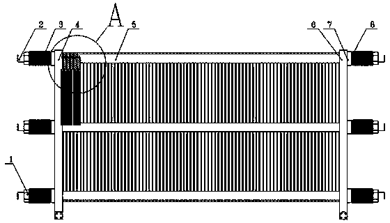
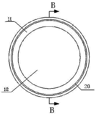
[0046] This embodiment provides an energy-saving high-pressure water electrolysis hydrogen production electrolyzer, which combines figure 1 with figure 2 , Including a flat cylindrical positive terminal plate 6 and a negative terminal plate 4 located at opposite ends, respectively. The positive terminal plate 6 and the negative terminal plate 4 are alternately arranged with flat cylindrical combined sealing gaskets 9 and poles. The plate frame assembly 10 is kept parallel. The screw 2 passes through the positive terminal plate 6 and the negative terminal plate 4 to fasten the combined sealing gasket 9 and the polar plate frame assembly 10. The two cylindrical end faces of the combined sealing gasket 9 are respectively provided A circular sealing lip sealing lip 20 eccentric to the center of the circle, a circular high-pressure sealing groove 21 is respectively provided on the two cylindrical end faces of the electrode plate frame assembly 10, and the sealing l...

Example Embodiment

[0051] Example 2:

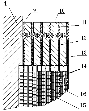
[0052] The combined seal 9 is composed of a ring-shaped rubber gasket 11 and a circular diaphragm asbestos cloth 12 located in the ring. The edge of the diaphragm asbestos cloth 12 and the inner edge of the rubber gasket 11 are integrated by a vulcanization hot pressing process The rubber gasket 11 is EPDM rubber, the diaphragm asbestos cloth 12 is a densely woven twill asbestos cloth specially used for water electrolysis hydrogen production, and the combination of the rubber gasket 11 and the diaphragm asbestos cloth 12 is the rubber gasket 11. When vulcanizing and compacting, place the outer ring of the diaphragm asbestos cloth 12 on the inner side of the rubber gasket 11, and simultaneously compress and vulcanize to ensure that the rubber gasket 11 and the diaphragm asbestos cloth 12 adhere firmly, and the length of the bonding part is 20-80mm.

[0053] A ring of sealing lips 20 biased toward the center of the rubber sealing gasket 11 is respectively provided...

Example Embodiment

[0057] Example 3:

[0058] Combine Image 6 , Figure 7 with Picture 9 , The pole plate frame assembly 10 is formed by welding a ring-shaped pole plate frame 13 and a circular pole plate assembly 14 located in the ring. The two ends of the pole plate frame 13 are provided with a seal lip 20 at the position corresponding to the sealing lip 20. Ring high-pressure sealing groove 21, the sealing lip 20 is embedded in the high-pressure sealing groove 21 with a movable gap; the opposite inner surfaces of the positive terminal plate 6 and the negative terminal plate 4 are also respectively provided with a ring for embedded sealing The high-pressure sealing groove 21 of the lip 20.

[0059] The outer diameter of the high-pressure sealing groove 21 is the same as the outer diameter of the sealing lip 20 on the rubber gasket 11, and the diameter is determined according to the designed electrolytic cell gas output. The depth of the high-pressure sealing groove 21 is 4-20mm and the width is 8...


PUM

PropertyMeasurementUnit
Heightaaaaaaaaaa
Wire diameteraaaaaaaaaa

Abstract

The invention relates to an energy-saving high-pressure water electrolysis hydrogen production tank. The energy-saving high-pressure water electrolysis hydrogen production tank is formed by combining and tensioning an anode end plate assembly, a cathode end plate assembly, a plurality of groups of circular polar plate frame assemblies and a plurality of groups of combined sealing gaskets with sealing lips by using a plurality of screw rods. Accessory polar plates are woven by using pure nickel wires and nickel-plated metal wires to form porous and multilayer combined grid plate structures with certain thickness and strength and are arranged at two sides of a veneer-type main polar plate; and a plurality of hexagonal or quadrangular gas and liquid channels are arranged in the radial and axial directions of each circular accessory polar plate. The accessory polar plates are fastened by using a plurality of stainless steel bolts arranged on the main polar plate. Due to the adoption of the structure, the gas and liquid can be kept smooth in the electrolysis process when the accessory polar plates are in a stressed state, the surface areas of the polar plates can be greatly increased, and the electrolysis efficiency can be increased. The energy-saving high-pressure water electrolysis hydrogen production tank is simple in structure and convenient and reliable in installation. Compared with the prior art, the energy-saving high-pressure water electrolysis hydrogen production tank has the characteristics of low manufacturing cost, energy saving, consumption reduction and the like so as to be an efficient and high-pressure novel water electrolysis hydrogen production tank.

Description

Technical field [0001] The invention relates to water electrolysis hydrogen production equipment, in particular to an energy-saving and high-pressure water electrolysis hydrogen production electrolyzer, which has the characteristics of high efficiency and energy saving and can withstand higher pressure. Background technique [0002] Hydrogen production by water electrolysis is a traditional hydrogen production method. The core part of water electrolysis hydrogen production equipment is the electrolyzer, which mainly consumes electricity and water. In today's world, the application and development of water electrolysis hydrogen production technology faces a wide range of challenges to reduce equipment operating power consumption and hydrogen production costs, improve the efficiency and versatility of market applications, and increase the service life and safety of equipment. Through long-term research and production practice, a consensus has been reached: Improving the electrode p...

Claims


Application Information

Patent Timeline
IPC IPC(8): C25B1/12C25B9/00C25B11/02
CPCY02E60/36
Inventor 何兴用王彦东杨炎
Owner 陕西华秦新能源科技有限责任公司
Why Eureka
Try Eureka