UHF (ultra high frequency) band type miniature microwave filter bank

A microwave filter and micro technology, applied in electrical components, multi-terminal pair network, impedance network, etc., to achieve the effect of simple circuit structure, mass production, and in-band flatness

Inactive Publication Date: 2015-09-30
NANJING UNIV OF SCI & TECH
View PDF4 Cites 5 Cited by
  • Summary
  • Abstract
  • Description
  • Claims
  • Application Information

AI Technical Summary

Problems solved by technology

But still do not have a kind of UHF band miniature microwave filter bank in the prior art

Method used


Image

  • UHF (ultra high frequency) band type miniature microwave filter bank
  • UHF (ultra high frequency) band type miniature microwave filter bank
  • UHF (ultra high frequency) band type miniature microwave filter bank

Examples


Embodiment Construction

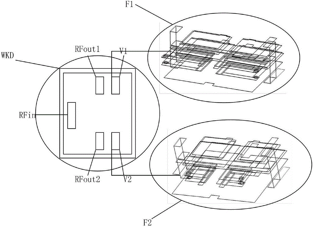
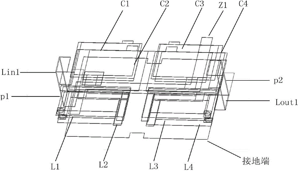
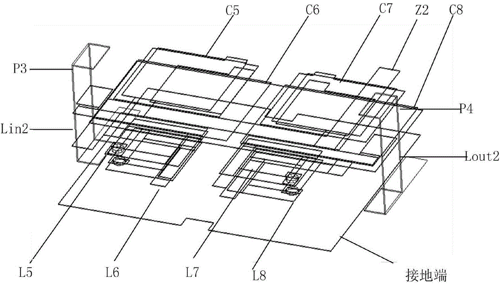
[0015] With reference to Fig. 1(a), Fig. 1(b) and Fig. 1(c), a UHF band miniature microwave filter bank of the present invention is presented. It includes a single-pole double-throw switch chip WKD102010UHF040 and two microwave filters. The first microwave filter F1 of the filter bank includes a surface-mounted 50-ohm impedance first input port P1, a first input inductance Lin1, and a first resonator L1 -C1, second resonator L2-C2, third resonator L3-C3, fourth resonator L4-C4, first output inductance Lout1, first Z-shaped interstage coupling stripline Z1, surface mount 50 Ohmic impedance of the first output port P2 and the ground terminal. Wherein, the first resonator L1-C1 is formed by connecting the first coil L1 and the first capacitor C1 in parallel, one end of the first coil L1 is connected to one end of the first capacitor C1, and the other end of the first coil L1 is connected to the first capacitor C1 The other ends of the two are respectively grounded; the second re...


PUM


Abstract

The invention relates to a UHF (ultra high frequency) band type miniature dual-microwave-filter bank. The dual-microwave-filter bank comprises a single-pole double-throw switch chip WKD102010040 and two microwave filters with different frequency bands and is obtained with a multi-layer LTCC (low temperature co-fired ceramic) technology. The miniature dual-microwave-filter bank has the advantages of easiness in debugging, light weight, small size, high reliability, good electrical property, good temperature stability, good batch consistency of electrical property, low cost, capability of realizing mass production and the like, and is applicable to occasions and corresponding systems, with strict requirements for size, electrical property, temperature stability and reliability, for communications in corresponding microwave frequency bands, satellite communications and the like.

Description

technical field [0001] The invention relates to a filter bank, in particular to a UHF band miniature microwave filter bank. Background technique [0002] In recent years, with the rapid development of miniaturization of mobile communication, satellite communication and national defense electronic systems, high performance, low cost and miniaturization have become the development direction of the microwave / radio frequency field. The performance, size and reliability of microwave filters Both sex and cost have put forward higher requirements. The main indicators describing the performance of this component are: passband operating frequency range, stopband frequency range, passband insertion loss, stopband attenuation, passband input / output voltage standing wave ratio, insertion phase shift and delay frequency characteristics, temperature Stability, size, weight, reliability, etc. Filters with different frequencies are connected through switches to form a filter bank, which c...

Claims


Application Information

Patent Timeline
Patent Type & Authority Applications(China)
IPC IPC(8): H03H7/01
Inventor 乔冬春张超戴永胜李博文刘毅潘航陈烨
Owner NANJING UNIV OF SCI & TECH
Why Eureka
Try Eureka