

Catalytic cracking device
A catalytic cracking unit and catalyst technology, which is applied in catalytic cracking, cracking, petroleum industry and other directions, can solve the problems such as the inability to effectively control the temperature of the regenerated catalyst, the long reaction time of raw materials, and the low ratio of operating agent to oil, etc. The effect of low content and improved yield
- Summary
- Abstract
- Description
- Claims
- Application Information
AI Technical Summary
Problems solved by technology
Method used
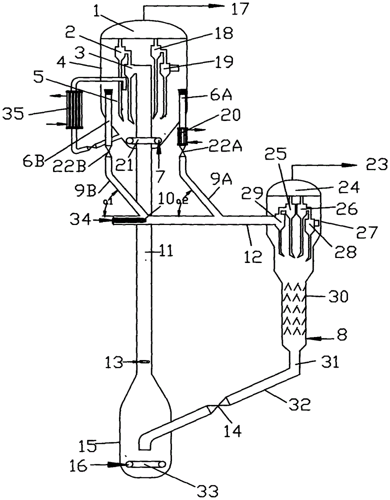
Image

Examples
Embodiment 1
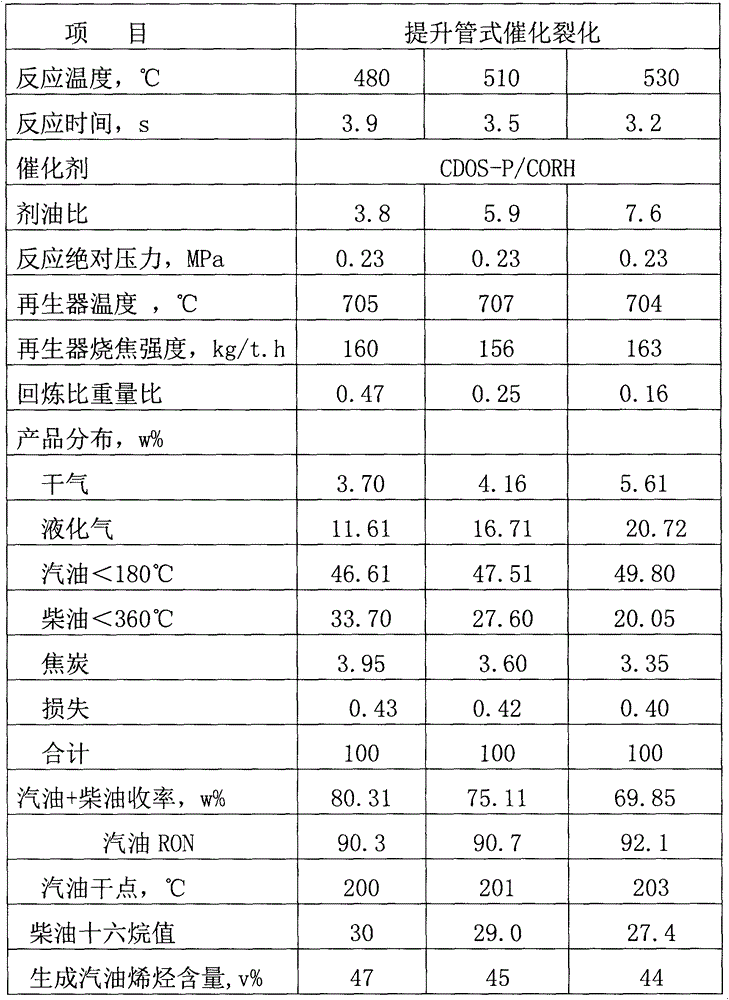
[0054] The catalytic cracking program is carried out on a catalytic cracking pilot plant with a raw material handling capacity of 72Kg / d. The test raw material is Luolian mixed wax oil, and the test catalyst is Luolian catalytic cracking industrial equilibrium catalyst. The micro-reaction activity is 62.
[0055] The raw catalyst is burnt by a coker and a tubular coker. The carbon content of the regenerated catalyst was 0.06w%, and the microreaction activity was 62. The stripping medium in the stripping section of the settler is water vapor, and the stripping temperature is 500°C.
[0056] The difference between this example and the comparative example is the temperature of the regenerated catalyst of the regenerated settler, the reaction temperature, the ratio of raw materials in the reactor to oil, and the reaction time.
[0057] The operating conditions, product distribution and some product properties of the present embodiment are shown in Table 3.
Embodiment 2
[0059] According to Example 1, the difference is the temperature of the regenerated catalyst of the regenerated settler, the reaction temperature, the ratio of raw materials to oil in the reactor, the reaction time, etc. The operating conditions, product distribution and part product properties of the present embodiment are shown in Table 4.
Embodiment 3
[0061] According to Example 1, the difference is the temperature of the regenerated catalyst of the regenerated settler, the reaction temperature, the ratio of raw materials to oil in the reactor, the reaction time, etc. The operating conditions, product distribution and some product properties of the present embodiment are shown in Table 5.
[0062] Table 1 Comparative examples of catalytic cracking feed properties
[0063] FCC Feed Feed
Luo Lian mixed wax oil
Density at 20°C, kg·m -3
901.2
Charcoal residue, w%
0.32
Family composition, w%
saturated hydrocarbon
57.5
Aromatics
39.8
Colloid + asphaltenes
2.7
Sulfur content, μg g -1
1700
Nitrogen content, w%
0.2706
Ni, μg g -1
2.6
V, μg·g -1
0.2
[0064] Table 2 Comparison of operating conditions, product distribution and some product properties of conventional catalytic cracking
[0065]
...
PUM
| Property | Measurement | Unit |
|---|---|---|
| diameter | aaaaa | aaaaa |
| height | aaaaa | aaaaa |
| diameter | aaaaa | aaaaa |
Abstract
Description
Claims
Application Information