
High-power semiconductor fiber-coupled laser and coupling method thereof

A fiber coupling and semiconductor technology, applied in the field of lasers, can solve the problems of multi-die coupling technology processing accuracy limitation, increased weight and material consumption, and limited number of coupling dies. It is easy to guarantee the processing accuracy, reduce packaging components, and structure Simple and lightweight effect

Active Publication Date: 2015-10-14
ANSHAN WONDER LIGHT LASER TECH CO LTD
View PDF6 Cites 24 Cited by
  • Summary
  • Abstract
  • Description
  • Claims
  • Application Information

AI Technical Summary

Problems solved by technology

[0004] The traditional multi-die coupling technology uses a stepped heat sink platform to realize the height difference of the beam in beam shaping. This process requires high machining accuracy of the stepped heat sink, usually around 10um, and the more steps there are , the greater the accumulated error, the multi-die coupling technology is directly limited by the machining accuracy of the step heat sink, and the number of coupled dies is limited and cannot be increased arbitrarily
[0005] For example, the Chinese patent application number 201310322502.1 (application date is July 29, 2013) discloses "a high-power semiconductor laser coupling optical fiber fixing device", all of its substrates, fast axis collimator FAC, slow axis The collimating mirror SAC and the reflector are respectively fixed on different steps of the base", the coupling effect is directly affected by the processing accuracy of the steps, and the use of large-area steps makes it more difficult to guarantee the processing accuracy; the application number is 201310322539.4 (the application date is The Chinese patent issued on July 29, 2013) discloses "an inclined plane multi-tube semiconductor laser coupling device and method". The purpose of "easy processing and high precision", but its structure is heavy and bulky, and its weight and material consumption will also increase significantly

Method used


Image

  • High-power semiconductor fiber-coupled laser and coupling method thereof
  • High-power semiconductor fiber-coupled laser and coupling method thereof
  • High-power semiconductor fiber-coupled laser and coupling method thereof

Examples


Embodiment Construction

[0023] The specific embodiment of the present invention will be further described below in conjunction with accompanying drawing:

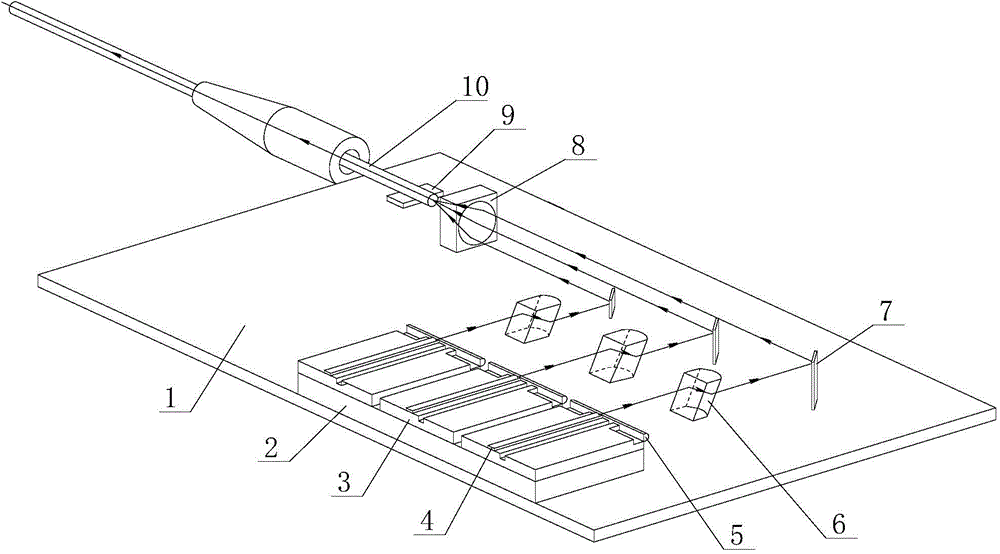
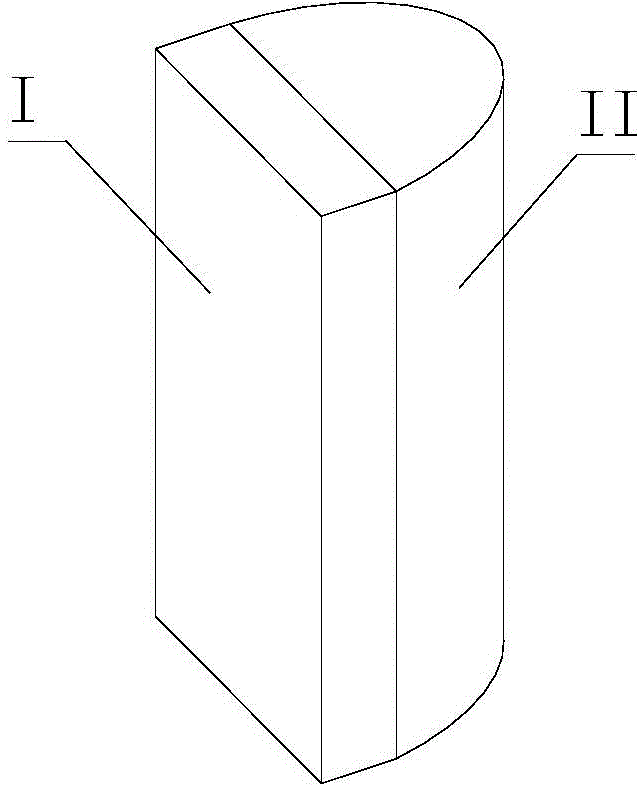
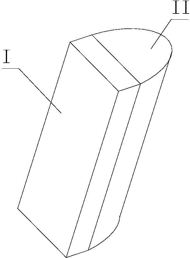
[0024] See figure 1 , is a structural schematic diagram of the high-power semiconductor fiber-coupled laser of the present invention, a high-power semiconductor fiber-coupled laser of the present invention includes a plurality of one-to-one corresponding laser diodes 4 integrated on the base plate 1, and a fast-axis collimating mirror FAC 5. The slow axis collimating mirror SAC 6 and the reflector 7 also include a focusing lens 8 and an optical fiber 10. The laser diode 4 is horizontally arranged at the same height, and its front end is provided with a fast axis collimating mirror FAC 5; the slow axis collimating mirror The SAC 6 is directly arranged on the base plate 1, and is a plano-convex lens inclined as a whole, and the thickness of each slow-axis collimator SAC 6 decreases successively along the distance from the focusing lens 8 from near t...


PUM


Abstract

The invention relates to a high-power semiconductor fiber-coupled laser and a coupling method thereof. Laser diodes are arranged at the same height level. Fast axis collimators FAC are arranged on the front ends. Slow axis collimators SAC are directly arranged on a bottom plate and are plano-convex lenses which integrally tilt. As the distance to a focusing lens is further, the thickness of the slow axis collimators SAC descends. The laser diodes produce a number of beams of the same height. Through the fast axis collimators FAC and the slow axis collimators SAC, high and low parallel beams are produced, are reflected to the focusing lens through the respective reflector, and are focused on a fiber. According to the invention, the slow axis collimators which integrally tilt are used to replace ladder heat sink to realize a height difference after beam adjusting; the processing accuracy is easily ensured; package components are reduced; the package difficulty is reduced; all components are horizontally arranged on the bottom plate; the laser has the advantages of simple and lightweight structure, small size, light weight and low material consumption; the number of coupled chips can be increased; and a laser of higher power can be produced.

Description

technical field [0001] The invention relates to a laser, in particular to a high-power semiconductor fiber-coupled laser and a coupling method thereof which can generate a height difference of a light beam by tilting a slow-axis collimating mirror SAC without a step heat sink. Background technique [0002] Multi-die coupling technology is an important part of semiconductor laser technology. Each single-die laser is coupled and combined into a laser beam with better beam quality and better efficiency. The coupling method determines the performance of high-power lasers. an important part of. [0003] Multi-die coupling technology generally includes steps such as fast axis shaping, slow axis shaping, beam shaping, focusing and coupling. Among them, the beam shaping is to adjust the light spot adjusted by the fast and slow axes according to a certain rule, and the smaller the spot area is, the more conducive the light beam is to be coupled into the optical fiber. [0004] The ...

Claims


Application Information

Patent Timeline
Patent Type & Authority Applications(China)
IPC IPC(8): H01S5/022H01S5/40H01S5/06
Inventor 魏敏何一平邵磊朱志刚
Owner ANSHAN WONDER LIGHT LASER TECH CO LTD
Learn More