
A movable jaw assembly of a mud pipeline crusher in a shield machine

A mud pipe and crusher technology, which is applied in the field of tunneling machinery, can solve problems such as the damage of the slurry pump, the blockage of the slurry outlet pipe of the mud-water circulation system, and the limitation of the tunneling capacity, so as to achieve the effect of preventing damage.

Active Publication Date: 2018-05-25
CHINA RAILWAY CONSTR HEAVY IND
View PDF8 Cites 0 Cited by
  • Summary
  • Abstract
  • Description
  • Claims
  • Application Information

AI Technical Summary

Problems solved by technology

When the shield machine is constructing tunnels in the water-rich strata with high content, high hardness, and large particle size pebbles in southwest, northwest, and north China, the crushing speed of the hydraulic jaw crusher in the air cushion cabin is only four per minute. times, and often damaged under harsh working conditions, it is impossible to quickly crush the pebbles with large flow and large particle size in the air cushion cabin to the conveying range of the slurry pump, and it is very easy for the shield machine to have pebbles in the air cushion cabin and muddy water Faults such as the blockage of the slurry outlet pipeline of the circulation system and the damage of the slurry discharge pump caused the shield machine to be shut down for maintenance for a long time, which greatly limited its excavation ability.
[0003] Therefore, the field needs to develop a new mud pipeline breaker to overcome the problem that the crushing capacity of the hydraulic jaw crusher in the above-mentioned air cushion cabin is too low, but the key part of the mud pipeline breaker is the sealing of the movable jaw assembly. Become a development difficulty in this field

Method used


Image

  • A movable jaw assembly of a mud pipeline crusher in a shield machine
  • A movable jaw assembly of a mud pipeline crusher in a shield machine
  • A movable jaw assembly of a mud pipeline crusher in a shield machine

Examples


Embodiment Construction

[0050] The specific implementation manner of the present invention will be briefly described below in conjunction with the accompanying drawings.

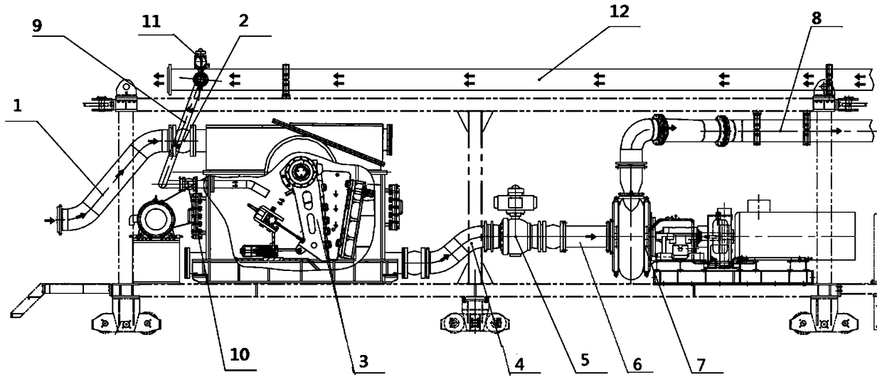
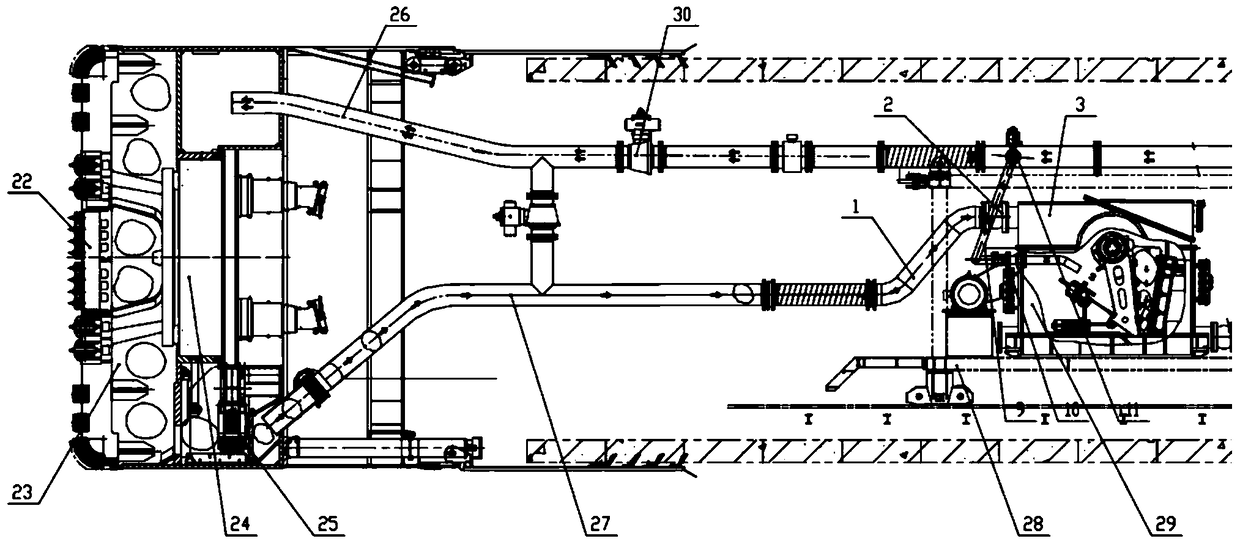
[0051] like figure 1 As shown, the mud-water circulation and stone-breaking system provided by the present invention includes a shield machine mud pipeline stone-breaking system 29, and the shield machine mud pipeline stone-breaking system includes a slurry discharge elbow-1, a large shock-absorbing throat 2, Mud pipeline crusher 3, slurry discharge elbow 2 4, large hydraulic ball valve 5, slurry discharge straight pipe 6, slurry discharge pump 7, slurry discharge elbow 3 8, flushing pipe 9, small shock-absorbing throat 10, small liquid Moving ball valve 11, crusher feed branch pipe 12. The working principle of the mud pipeline gravel system of the shield machine of the present invention is as follows: the left end slurry inlet of the mud pipeline crusher 3 with the function of sealing high-pressure mud and crushing large-sized pe...


PUM


Abstract

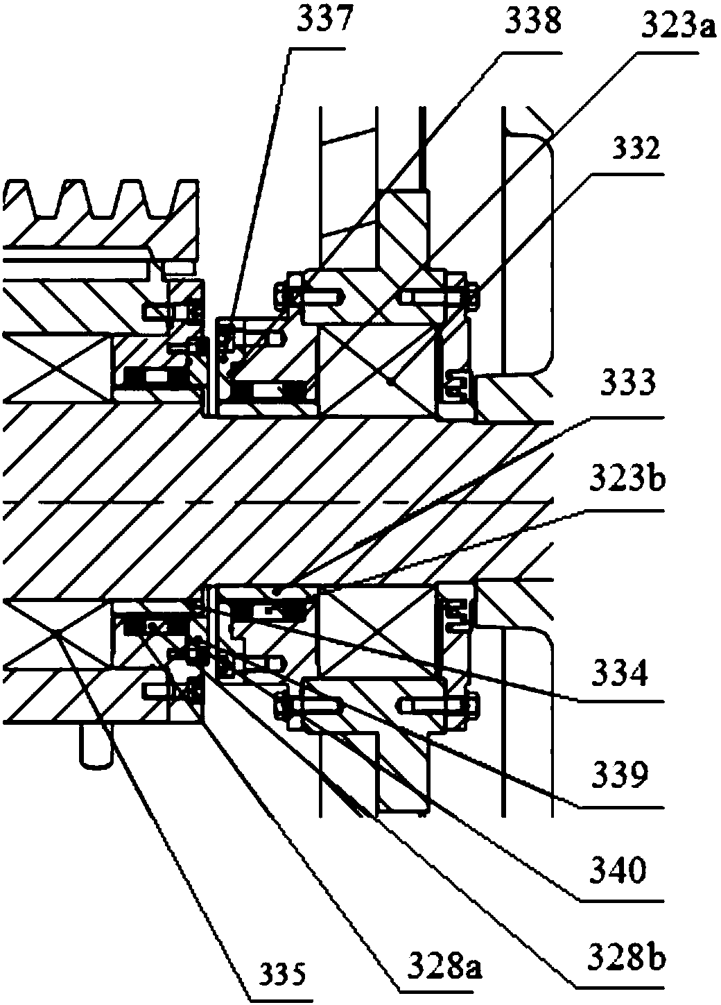
The invention provides a movable jaw assembly of a mud pipeline crusher in a shield machine. The movable jaw assembly includes an eccentric shaft driven by a motor to rotate, and is fixedly arranged outside the axial direction of the eccentric shaft for connecting the movable jaw assembly to a machine frame. The outer bearing and bearing seat on the eccentric shaft, the inner bearing fixedly arranged on the axial inner side of the eccentric shaft, the movable jaw connected to the inner bearing, the movable jaw plate connected to the movable jaw, and the outer bearing rotating seal ring parts, outboard bearing rotary seal, inboard bearing rotary seal ring and inboard bearing rotary seal. The present invention uses a dynamic sealing structure to replace the bearing sealing structure in the traditional movable jaw assembly. On the one hand, the movable jaw assembly provided by the present invention effectively prevents its internal shaft transmission parts from being damaged under the state of high-pressure fluid gravel, and the movable jaw assembly provides a feasible dynamic The sealing method enables the mud pipeline breaker to work continuously and stably in underground engineering.

Description

technical field [0001] The invention belongs to the technical field of tunneling machinery, and in particular relates to a movable jaw assembly of a mud pipeline breaker in a shield machine. Background technique [0002] From the front end of the excavation position to the rear end of the shield machine, it consists of an excavation cabin containing a cutter head, an air cushion cabin and a trailer. The main purpose of the air cushion cabin is to balance and stabilize the excavation surface. At present, in the process of tunnel excavation by the shield machine in the water-rich sand and pebble stratum using the mud-water balance method, it is necessary to remove the muck through the mud-water circulation system and maintain the stability of the excavation surface; at this time, the shield machine dregs method is: The muck and pebbles after disc cutting and the mud injected from outside the tunnel are mixed in the excavation cabin to form a fluid that enters the air cushion c...

Claims


Application Information

Patent Timeline
Patent Type & Authority Patents(China)
IPC IPC(8): B02C1/02
Inventor 刘飞香程永亮任锦江麻成标容锦张社军范瑞强文中保彭帅王海明
Owner CHINA RAILWAY CONSTR HEAVY IND
Learn More