Tool with coating film and manufacturing method thereof
A manufacturing method and cutting tool technology, which are applied to coated cutting tools and their manufacturing fields, can solve the problems of poor bonding force between the coating and the substrate, poor wear resistance, etc. Effect
- Summary
- Abstract
- Description
- Claims
- Application Information
AI Technical Summary
Problems solved by technology
Method used
Image

Examples
Embodiment 1
[0049] In this embodiment, a coated kitchen knife is produced, and the production process is as follows:
[0050] Step 1. Provide the substrate
[0051] 1. Blade stamping, the base material is 3Cr13 martensitic stainless steel;
[0052] 2. Conventional heat treatment for the blade: quenching temperature 1050°C, heating for 50 minutes, cooling for 70 minutes; tempering temperature 150-230°C, heat preservation for 2-3 hours;
[0053] 3. The blade is obliquely ground, sharpened and aligned;
[0054] Step 2. Remove oil and oxide impurities on the surface of the substrate
[0055] 1. The blade is pre-cleaned, and the cleaning method is ultrasonic vibration cleaning. Use ethanol to vibrate and wash for many times to remove the dirt on the surface of the blade, and then dry it after vibrating for many times.
[0056] 2. Use high pressure N 2 The air gun blows the blade directly to prevent the suspended particles in the air from adhering to the surface of the blade.
[0057] 3. ...
Embodiment 2
[0062] In this embodiment, a coated kitchen knife is produced, and the manufacturing process is the same as that in Example 1, the differences are as follows:
[0063] Step 3. Double-sided coating on the blade edge
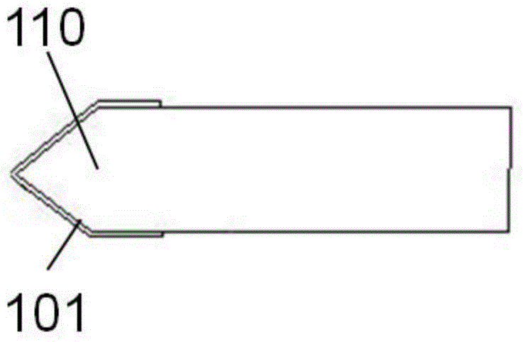
[0064] Put the blade into a vacuum chamber, and use graphite and titanium targets to deposit amorphous carbon film and Ti ions by FCVA method. The angle between the substrate and the ion source is 45°, the ion beam energy is 600eV, and the beam current is 2.5mA / cm 2 , elbow current 8A, deposition bias -110V, deposition speed 300s, deposition thickness 12.36nm, take a cross-section along the thickness direction of the edge of the hydrogen-free amorphous carbon film away from the blade, and the distance between the tip of the blade and the cross-section is 10mm.
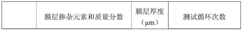
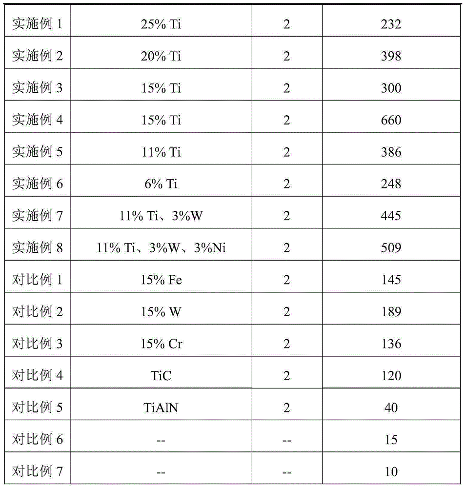
[0065] The parameters of the finally formed hydrogen-free amorphous carbon film are shown in Table 1.
Embodiment 3
[0067] In this embodiment, a coated kitchen knife is produced, and the manufacturing process is the same as that in Example 1, the differences are as follows:
[0068] Step 3. Double-sided coating on the blade edge
[0069] Put the blade into a vacuum chamber, and use graphite and titanium targets to deposit amorphous carbon film and Ti ions by FCVA method. The angle between the matrix and the ion source is 41°, the ion beam energy is 580eV, and the beam current is 2.6mA / cm 2 , elbow current 8A, deposition bias -100V, deposition speed 300s, deposition thickness 12.36nm, take a cross-section in the thickness direction along the edge of the hydrogen-free amorphous carbon film away from the blade, and the distance between the tip of the blade and the cross-section is 10mm.
[0070] The parameters of the finally formed hydrogen-free amorphous carbon film are shown in Table 1.
PUM
 Abstract
Description
Claims
Application Information
 - Generate Ideas
- Intellectual Property
- Life Sciences
- Materials
- Tech Scout
- Unparalleled Data Quality
- Higher Quality Content
- 60% Fewer Hallucinations
Browse by: Latest US Patents, China's latest patents, Technical Efficacy Thesaurus, Application Domain, Technology Topic, Popular Technical Reports.
© 2025 PatSnap. All rights reserved.Legal|Privacy policy|Modern Slavery Act Transparency Statement|Sitemap|About US| Contact US: help@patsnap.com