
Method and device for gasifying feedstock

A raw material, gasifier technology, applied in mechanical equipment, gasification process, combustion method, etc., can solve problems such as hindering the total amount of raw materials, low efficiency, inconsistent quality, etc.

Inactive Publication Date: 2015-11-04
PHG ENERGY
View PDF5 Cites 5 Cited by
  • Summary
  • Abstract
  • Description
  • Claims
  • Application Information

AI Technical Summary

Problems solved by technology

[0011] Current downdraft gasification processes have some significant drawbacks that prevent widespread adoption
These disadvantages are: (1) The feedstock must be pre-processed into standard sizes with similar chemical properties (no mixing of different types of feedstock or fragments of different sizes) to enable continuous gasification without traversing (i.e. plugging) equipment or Affect the quality of producer gas; (2) The volatile composition of the raw material must be within the standard range; (3) The raw material must have a standard calorific content (ie btu / lb); (4) Usually, the gasifier must be stopped frequently, To clean up and remove the excess coal coke accumulated at the bottom of the gasifier; (5) The quality of the producer gas produced is inconsistent, and due to frequent shutdowns resulting in temperature changes and changes in raw materials, the productivity and efficiency of the gasifier are low; (6) The gasifier cannot be reconfigured during operation, and once the oxidation reaction deviates from the designated position in the gasifier, the gasifier must be shut down; (7) The gasifier cannot maintain thermal stability for a long time. Loss of efficiency (or melting); and (8) the gasifier does not allow the location of the oxidation reaction to be moved in series with the reduction zone to compensate for the different conditions required for the gasification of different types of feedstock and resulting differences in the composition of the producer gas Proportion
Unfortunately, the restricted area of ​​current gasifiers significantly hampers the total amount of feedstock that can pass through such gasifiers and affects the overall flow and production of producer gas

Method used


Image

  • Method and device for gasifying feedstock
  • Method and device for gasifying feedstock
  • Method and device for gasifying feedstock

Examples


Embodiment Construction

[0041] definition

[0042] The following defined terms are not limiting or comprehensive, but are provided as a quick reference tool for understanding the present invention. Other defined terms used elsewhere in this document are capitalized. Capitalized terms include all inflections, singular and / or plural forms of the terms employed herein.

[0043] "Bed Oxidant Stream" or "Bed Air" means an oxidant stream that enters a gasifier through an inlet (i.e., a non-flat inlet) that is located in the pyrolysis zone (or can selected drying zone) top.

[0044] "Biochar" means the carbon ash and residue by-products formed when biomass feedstock is gasified.

[0045] "Bypass" means the "gap" between the top of the grate below the gasifier and the opening at the bottom of the reduction zone, also known as the grate pitch.

[0046] By "control system" is meant an operating system comprising multiple control mechanisms and coordinating software for the user / operator to adjust gasifier ...


PUM


Abstract

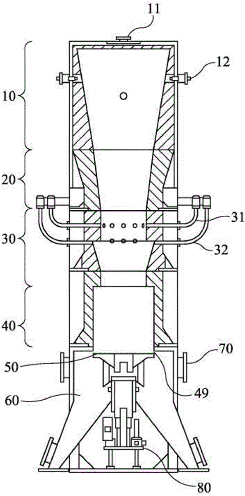
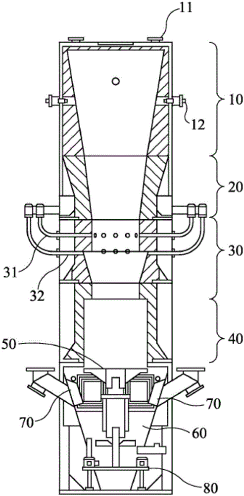
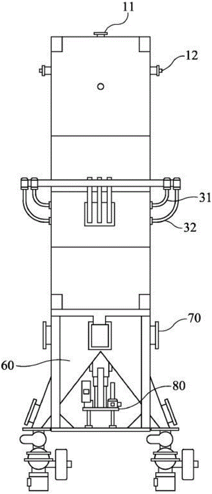
A downdraft gasifier and method of gasification that utilizes a plurality of vertically positioned tubes to create a pyrolysis zone, an oxidation zone beneath the pyrolysis zone and a reduction zone beneath the oxidation zone. The shape of the tubes eliminates the need for a restriction (hearth), which limits the maximum achievable throughput. A rotating and vertically adjustable grate is located beneath, but not attached to, the reduction zone of the gasifier.

Description

technical field [0001] The invention relates to thermochemical technology and equipment, in particular to a process and equipment for gasifying solid biomass, domestic and industrial waste, fossil fuels and other carbon-containing raw materials by adopting downdraft gasification. Background technique [0002] Gasification is a continuous thermal decomposition process in which organic solid or carbonaceous material (feedstock) is decomposed into a combustible gas mixture. The combustible gas components produced mainly include carbon monoxide (CO), hydrogen (H 2 ) and methane (CH 4 ). Also contain varying amounts of other non-flammable gases such as nitrogen (N 2 ), water vapor (H 2 0) and carbon dioxide (CO 2 ). The gasification process involves pyrolysis followed by partial oxidation, controlled by injecting air or other oxygen-containing gas into the partially pyrolyzed feedstock. More specifically, biomass gasification is a series of reactions including water evapor...

Claims


Application Information

Patent Timeline
Patent Type & Authority Applications(China)
IPC IPC(8): F02C1/00
CPCF23G5/26C10J3/26C10J3/42C10J2300/0916F23G5/027F23G2900/50002F23G5/245F23G5/002
Inventor 德翁·乔赫恩·坡特吉埃特比利·弗里曼·霍珀杰弗里·斯科特·布朗马克·奥利弗·洛夫廷
Owner PHG ENERGY
Learn More