
Method and system for time synchronization calibration of wireless sensor network

A wireless sensor network and time synchronization technology, applied in time division multiplexing systems, electrical components, multiplexing communication, etc., can solve clock frequency deviation, poor convergence of synchronization results, and poor local clock Track the standard clock and other issues to achieve the effect of improving accuracy, reducing energy loss, and minimizing control energy

Inactive Publication Date: 2015-11-18
PHICOMM (SHANGHAI) CO LTD
View PDF2 Cites 10 Cited by
  • Summary
  • Abstract
  • Description
  • Claims
  • Application Information

AI Technical Summary

Problems solved by technology

[0005] In view of the shortcomings of the prior art described above, the purpose of the present invention is to provide a time synchronization calibration method and system for a wireless sensor network, which is used to solve the problem of using the PTP time synchronization algorithm to correct the local clock time in the prior art. Due to the existence of observation errors, coupled with the deviation of the local clock frequency, the synchronization result does not converge well, and the local clock cannot track the standard clock well.

Method used


Image

  • Method and system for time synchronization calibration of wireless sensor network
  • Method and system for time synchronization calibration of wireless sensor network
  • Method and system for time synchronization calibration of wireless sensor network

Examples


Embodiment 1

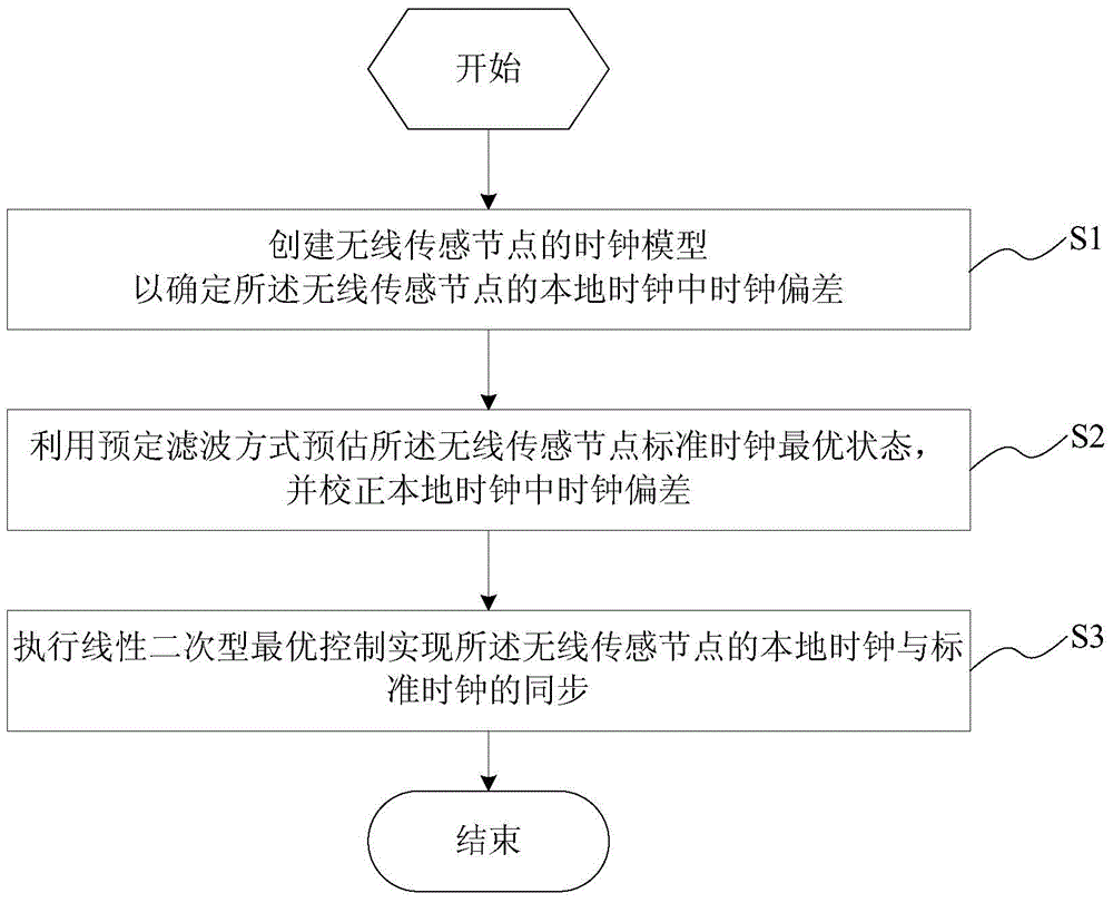
[0041] This embodiment provides a time synchronization calibration method for a wireless sensor network, where the wireless sensor network includes several wireless sensor nodes. see figure 1 , is shown as a schematic flow chart of the time synchronization calibration method for wireless sensor networks. Such as figure 1 As shown, the time synchronization calibration method of the wireless sensor network includes the following steps:

[0042] S1. Create a clock model of the wireless sensor node to determine a clock bias in a local clock of the wireless sensor node. In the wireless sensor network, each wireless sensor node has its own local clock, and the accuracy of the local clock is determined by the frequency of the local crystal oscillator and the clock threshold. The ideal clock model of wireless sensor nodes can be expressed as:

[0043] C(t)=t formula (1)

[0044] Among them, t represents time.

[0045] However, due to the imperfection of the nodal crystal oscilla...

Embodiment 2

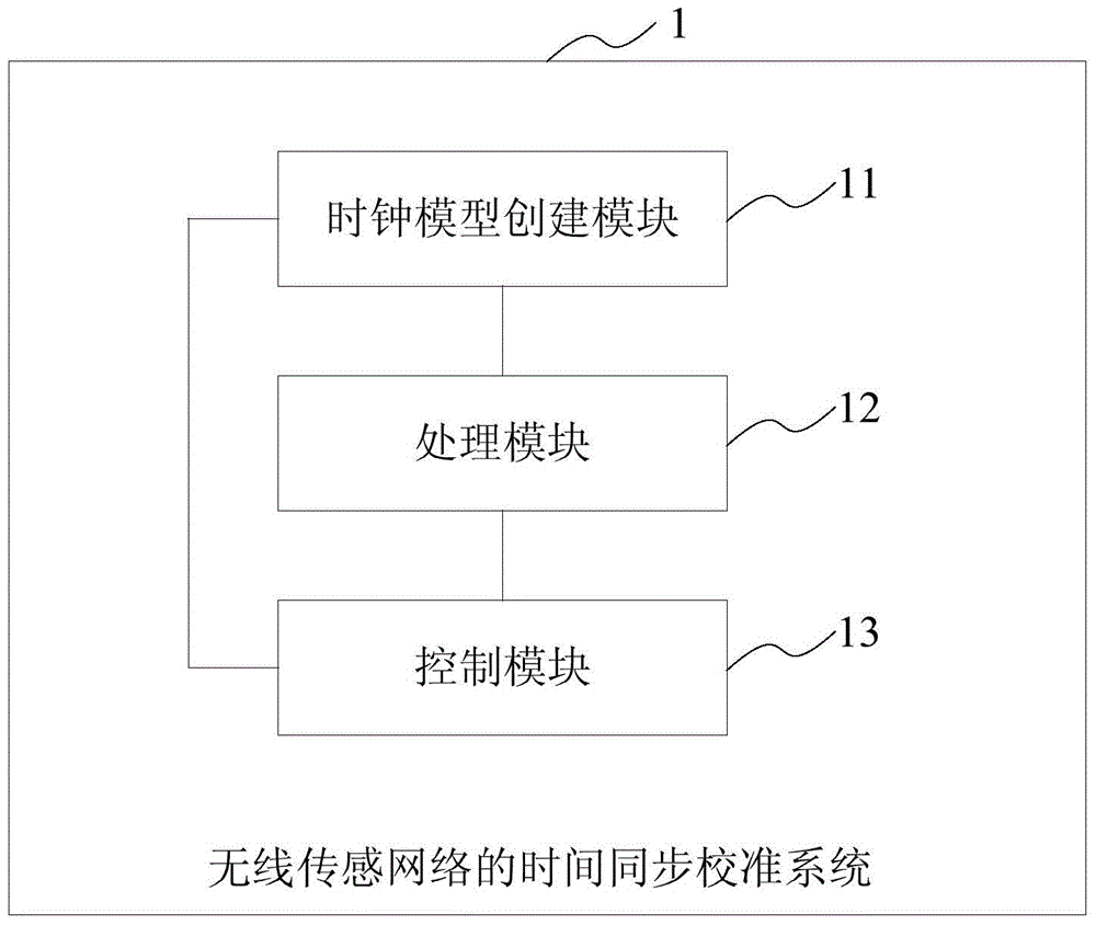
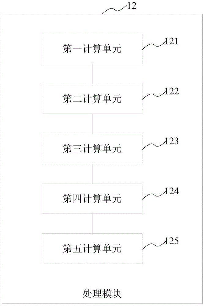
[0078] This embodiment provides a time synchronization calibration system for a wireless sensor network, where the wireless sensor network includes several wireless sensor nodes. see figure 2 , is shown as a schematic diagram of the principle structure of a time-synchronized calibration system for wireless sensor networks. Such as figure 2 As shown, the time synchronization calibration system of the wireless sensor network includes: a clock model creation module 11 , a processing module 12 , and a control module 13 .

[0079] The clock model creation module 11 is used to create a clock model of the wireless sensor node to determine the clock bias in the local clock of the wireless sensor node. In the wireless sensor network, each wireless sensor node has its own local clock, and the accuracy of the local clock is determined by the frequency of the local crystal oscillator and the clock threshold. The ideal clock model of wireless sensor nodes can be expressed as:

[0080...


PUM


Abstract

The invention provides a method for time synchronization calibration of a wireless sensor network, wherein the wireless sensor network comprises a plurality of wireless sensor nodes. The method comprises the following steps of: creating a clock model of the wireless sensor nodes to determine clock skew in a local clock of the wireless sensor nodes; estimating optimal state of a standard clock of the wireless sensor nodes by a predetermined filtering mode, and calibrating the clock skew in the local clock; executing linear quadratic optimal control to realize synchronization of the local clock and the standard clock of the wireless sensor nodes. According to the invention, firstly, standard time information received by the nodes is subjected to noise filtering by Kalman filtering, precision of the standard block is improved, and consequently, precision of local time synchronization is improved effectively; then, by a linear quadratic tracking method of optimum control, under premise of ensuring system stability, error is kept around zero with the cost of lower control energy, and the aim of time synchronization is achieved.

Description

technical field [0001] The invention belongs to the technical field of wireless sensor networks, and relates to a calibration method and system, in particular to a time synchronization calibration method and system of a wireless sensor network. Background technique [0002] ZigBee network has received high attention due to its high monitoring accuracy, low power consumption and cost, low complexity and flexible deployment. It is used in many fields such as smart home, industrial control, military reconnaissance, intelligent transportation, and environmental monitoring. Has a very wide range of applications. However, because the monitoring environment is generally complex and unstable, the nodes are generally powered by batteries, making it difficult to supply energy. The continuous working time of the nodes has become a key issue restricting the network. How to save energy consumption has become the key to the design of wireless sensor networks. IEEE1588 is a precise clock ...

Claims


Application Information

Patent Timeline
Patent Type & Authority Applications(China)
IPC IPC(8): H04J3/06
Inventor 朱培
Owner PHICOMM (SHANGHAI) CO LTD
Learn More