Cutting liquid recycling equipment and recycling method thereof

A technology for recycling equipment and cutting fluid, applied in cutting fluid recycling equipment and its recycling field, can solve the problems of waste liquid sewage discharge, peeling, cutting fluid odor, etc., to reduce human resources, improve processing efficiency, and reduce emissions. Effect

Inactive Publication Date: 2015-11-25
SHENZHEN TIANDEYI ENVIRONMENT TECH
View PDF8 Cites 9 Cited by
  • Summary
  • Abstract
  • Description
  • Claims
  • Application Information

AI Technical Summary

Problems solved by technology

There are two types of bacteria, aerobic bacteria and anaerobic bacteria, no matter which type will cause foul smell and bacterial pollution to the cutting fluid, which will seriously endanger the working environment and increase the loss of cutting fluid
[0005] 3) The harm of floating oil is that some materials in the cutting fluid system expand and deform, disturb the emulsification balance of the emulsion, and cause the emulsion to lose stability; and the floating oil often floats on the surface of the emulsion oil, blocking the emulsion and air. Contact, resulting in the lack of oxygen in the emulsion, rapid reproduction of anaerobic bacteria, and accelerated spoilage of the emulsion
[0006] 4) At present, in the normal loss of cutting fluid in the market and processing factories, most of the processing factories currently use manual preparation, manual addition and waste liquid cleaning, which is labor-intensive and tedious
[0007] Therefore, the current cutting fluid in the processing industry has the problems of unreasonable addition methods, waste liquid loss and sewage discharge. The machine tool operator’s skin is infected by bacteria when the machine tool operator is in contact with the deteriorated cutting fluid during the processing process. The festering situation will cause great harm to the machine tool operator.

Method used


Image

  • Cutting liquid recycling equipment and recycling method thereof
  • Cutting liquid recycling equipment and recycling method thereof
  • Cutting liquid recycling equipment and recycling method thereof

Examples


Embodiment Construction

[0046] In order to express the present invention more clearly, the present invention will be further described below in conjunction with the accompanying drawings.

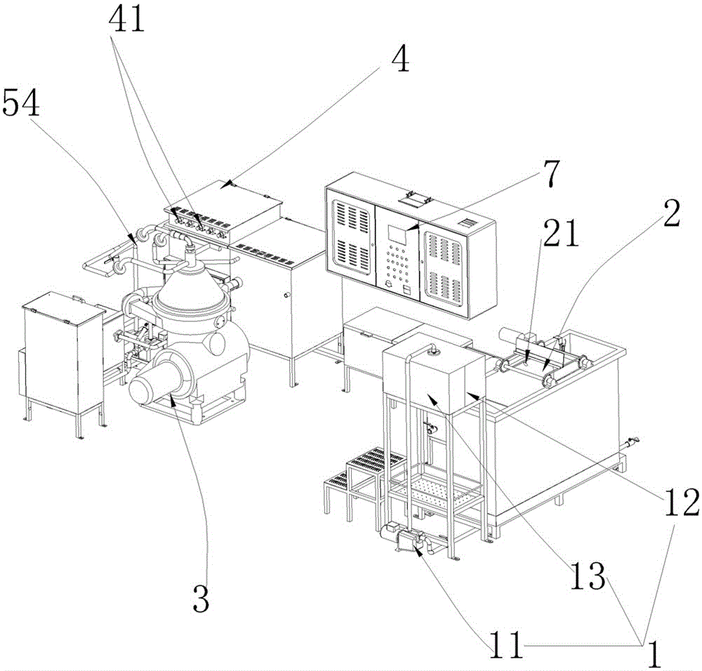
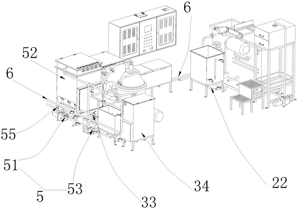
[0047] see Figure 1-2, the cutting fluid recycling equipment provided by the present invention includes an automatic feeding device 1, a dissolved air flotation machine 2, a high-speed centrifuge 3, a UV photolysis sterilization device 4, an automatic discharging device 5 and a PLC controller (not shown in the figure) ); the automatic feeding device 1 is provided with a feed pump 11 and a feed transfer box 13 with a filter screen 12 inside, and the automatic discharge device 5 is provided with a discharge pump 51 and a discharge box 52, and the feed pump 11 and discharge pump 51 are electrically connected with the output end of the PLC controller respectively;

[0048] The feed pump 11 feeds the waste cutting fluid into the feed transfer box 13 and passes through the filter screen 12 to roughly filter the coarse...


PUM


Abstract

The invention discloses cutting liquid recycling equipment and a recycling method thereof. The equipment comprises an automatic loading device, a dissolved air flotation machine, a high-speed centrifuge, a UV photolytic sterilization device, an automatic discharge device and a PLC, wherein the automatic loading device is provided with a feed pump and a feed transfer box having a filter screen inside; a discharge pump and a discharge box are arranged on the automatic discharge device; and the feed pump and the discharge pump are respectively in electric connection with the output end of the PLC. The equipment can reduce the manpower resource and the labor intensity while improving the treatment efficiency, reduces the industrial sewage emission, and can clearly distinguish cutting liquid, waste oil and waste slag; and recovered materials are free of bacteria and stink, so that the production efficiency and data and the production environment and the treatment clearness are maximal, and users clearly master the operation conditions of the equipment.

Description

technical field [0001] The invention relates to the technical field of industrial cutting fluid treatment, in particular to a cutting fluid circulation recovery device and a recovery method thereof. Background technique [0002] In the process of mechanical processing, a large amount of metal cutting fluid is required, referred to as cutting fluid. Whether it is imported or domestic water-based cutting fluid or emulsion, in routine use, problems such as deterioration of cutting fluid and waste liquid treatment and discharge will be encountered; the main There are the following defects: [0003] 1) During the working process of the machine tool, there will be a large amount of guide oil, spindle oil, hydraulic oil, solid waste, iron filings, powder, dust and other sundries mixed into the cutting fluid, which will easily lead to blockage of the machine tool liquid circulation route . [0004] 2) Waste cutting fluid contains a large number of bacteria and microorganisms, and ...

Claims


Application Information

Patent Timeline
Patent Type & Authority Applications(China)
IPC IPC(8): B23Q11/00B01D36/00C10M175/00
CPCB01D36/00B01D36/006B01D36/045C10M175/00Y02P70/10
Inventor 周芳玉沈震郑仁武
Owner SHENZHEN TIANDEYI ENVIRONMENT TECH
Why Eureka
Try Eureka