
Phase change heat storage device

A phase-change heat storage and heat exchange device technology, applied in heat storage equipment, heat exchange equipment, heat exchanger types, etc., can solve the problems of poor temperature uniformity of heat accumulators, increased mixing and redistribution, and limited heat storage efficiency. , to achieve the effect of isotropic specific strength, high specific strength and good thermal conductivity

Active Publication Date: 2015-12-02
SOUTHEAST UNIV
View PDF17 Cites 12 Cited by
  • Summary
  • Abstract
  • Description
  • Claims
  • Application Information

AI Technical Summary

Problems solved by technology

[0003] Technical problem: In order to solve the problems of poor heat accumulator temperature uniformity, low heat storage density, and limited heat storage efficiency in the design of existing heat storage devices, the present invention provides a heat exchanger through continuous shunting, turbulence, and confluence effects. The heat in the heat pipe is quickly and evenly dispersed and transferred in the entire heat accumulator space along the channel of the high heat conduction channel array, so as to increase the mixing and redistribution of the phase change heat storage device in the process of heat flow transfer, and then make the entire heat storage The temperature distribution of the heat storage device is more uniform, which greatly improves the heat storage density and heat storage efficiency of the heat storage device, so that the heat storage and heat release process of the heat storage device can be carried out stably and efficiently.

Method used


Image

  • Phase change heat storage device
  • Phase change heat storage device
  • Phase change heat storage device

Examples


Embodiment Construction

[0033] The present invention will be further described in detail below in conjunction with the accompanying drawings.

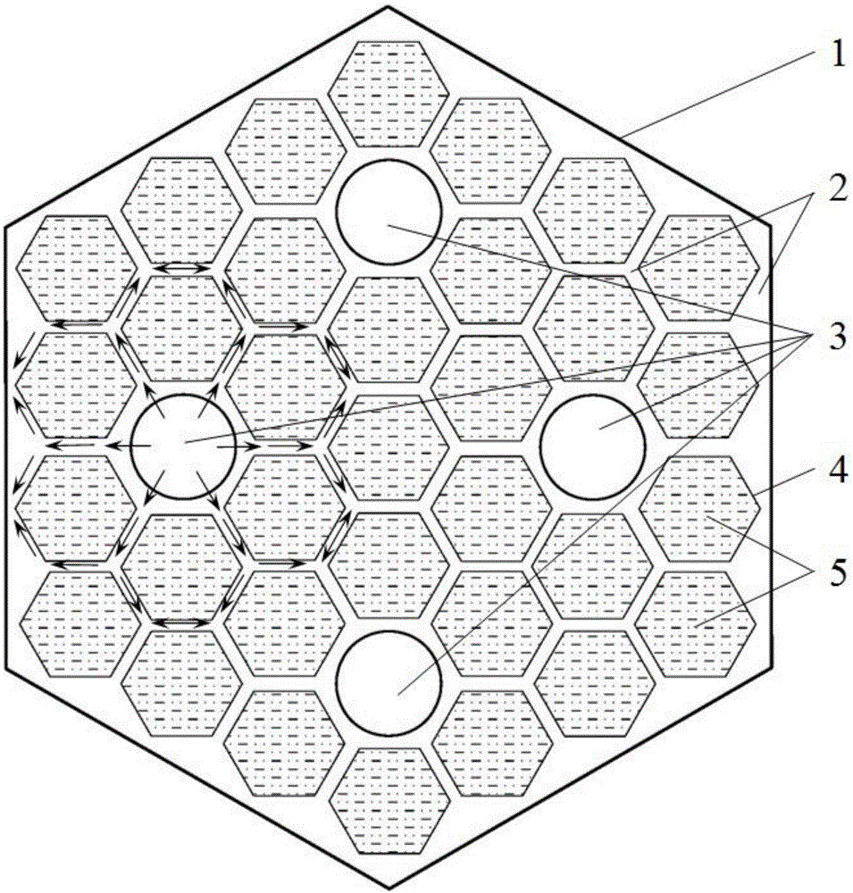
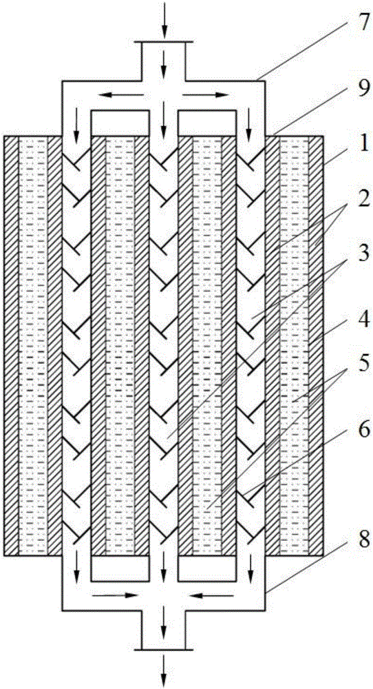
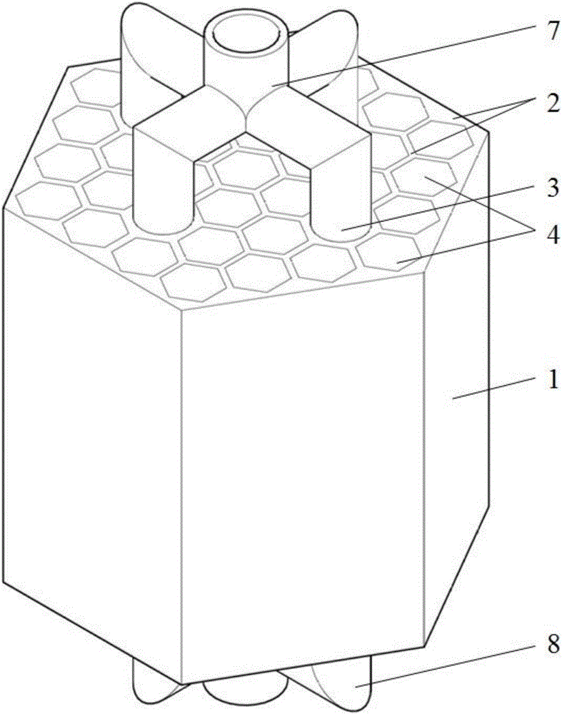
[0034] figure 2 , image 3 A schematic diagram of the overall structure of the heat accumulator is given, a solid-liquid phase change heat accumulator, which consists of a heat exchanger shell 1, a metal skeleton 2, a heat exchange pipe 3, a phase change material filling channel 4, and a phase change heat accumulator. The thermal material 5, the chaotic spoiler 6, the flow diversion device 7, the current collection device 8 and the thermal insulation material 9 are composed. figure 1 A schematic diagram of the arrangement structure of the metal skeleton channels and heat exchange pipes of the regenerator is given. The metal skeleton 2 is a hexagonal prism structure with multiple channels. The channels 4 are arranged in parallel according to the imitation honeycomb structure. The hexagonal channels evenly pave the entire heat storage section, effectively ut...


PUM


Abstract

The invention discloses a phase change heat storage device. The phase change heat storage device comprises a heat accumulator shell, heat exchange pipelines and phase change materials, wherein the heat exchange pipelines and the phase change materials are arranged in the heat accumulator shell. The phase change heat storage device is characterized in that a porous metal framework is arranged in the heat accumulator shell, porous channel arrays are arranged on the porous metal framework in parallel in the axial direction, and the phase change materials are located in all porous channels of the porous channel arrays; the heat exchange pipelines are arranged in the porous channel arrays in the axial direction of the porous metal framework at intervals; each heat exchange pipeline is surrounded by at least one circle of pore channels; a flow dividing device is arranged at inlets of the heat exchange pipelines, and a flow collecting device is arranged at outlets of the heat exchange pipelines; three-dimensional crossed flow guide type chaos turbulators are further arranged in the heat exchange pipelines. According to the phase change heat storage device, due to the fact that the three-dimensional crossed flow guide type chaos turbulators are arranged in the heat exchange pipelines, flow guide blocks which are arrayed periodically and alternately can induce fluid to generate chaos convection, heat exchange between the fluid and pipe walls can be enhanced obviously, and the heat storage device can achieve excellent heat storage and heat exchange capability.

Description

technical field [0001] The invention relates to an energy storage and release device, in particular to a device for heat storage and heat exchange through solid-liquid phase change materials. Background technique [0002] The development of new high-efficiency and energy-saving technologies has become an important research topic in the field of engineering thermophysics. In the process of industrial waste heat utilization, the development of high-efficiency heat storage technology is an important technical approach to solve the mismatch between energy demand and supply and improve energy utilization. At present, there are mainly three types of heat storage methods: latent heat storage, sensible heat storage and chemical reaction heat storage. Latent heat storage realizes the storage and release of energy through the phase change process of phase change materials (PCM). Commonly used heat storage means. However, most of the existing latent heat storage structures use singl...

Claims


Application Information

Patent Timeline
IPC IPC(8): F28D20/02F28F9/24
CPCY02E60/14
Inventor 陈永平张孟臣朱炳朋张程宾
Owner SOUTHEAST UNIV
Learn More