Time-window-enthalpy-value-integral-based smoke cooling control method and system

A technology of flue gas cooling and control method, applied in general control system, control/adjustment system, adaptive control, etc., can solve the problems of frequent action, tower body wall, adhesion, etc.

Active Publication Date: 2015-12-02
HUATIAN ENG & TECH CORP MCC
View PDF7 Cites 2 Cited by
  • Summary
  • Abstract
  • Description
  • Claims
  • Application Information

AI Technical Summary

Problems solved by technology

[0009] Both methods have limitations in practical application: if only the outlet temperature is used to adjust the rod, the sprayed water flow cannot keep up with the change of the flue gas flow and temperature due to the hysteresis of the temperature measurement; if the inlet temperature and the If the temperature difference of the target temperature is used to calculate the enthalpy to adjust the water volume, the flue gas flow rate and temperature at the inlet of the tower body will change drastically, which will inevitably cause a drastic change in the calculated value of the enthalpy of the instantaneous response, which will cause frequent actions of the control valve and instantaneous temperature overshoot. The overshoot will cause the excess cooling water to be sprayed onto the tower wall, causing the dust in the flue gas to stick on the tower wall, resulting in the wall of the tower over time.

Method used


Image

  • Time-window-enthalpy-value-integral-based smoke cooling control method and system
  • Time-window-enthalpy-value-integral-based smoke cooling control method and system
  • Time-window-enthalpy-value-integral-based smoke cooling control method and system

Examples


Embodiment 1

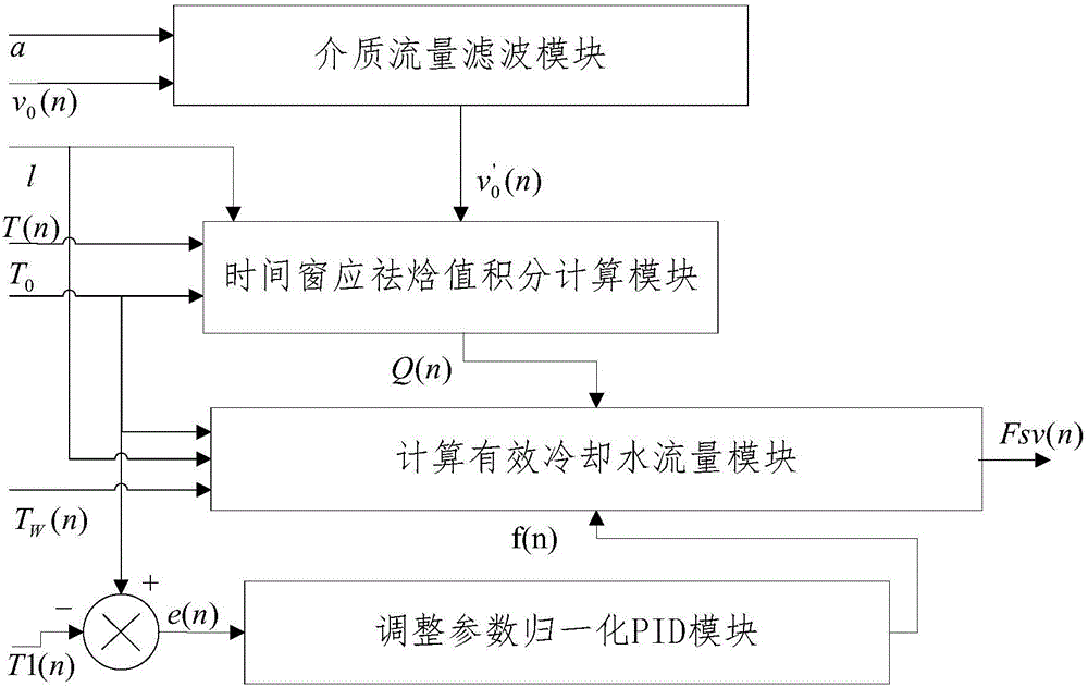
[0117] In this embodiment, the flue gas cooling control system based on time window enthalpy integration includes 4 program modules:

[0118] (1) Medium flow filter module

[0119] (2) Time window response enthalpy integral calculation module

[0120] (3) Calculate effective cooling water flow module

[0121] (4) Adjust the parameters to normalize the PID module

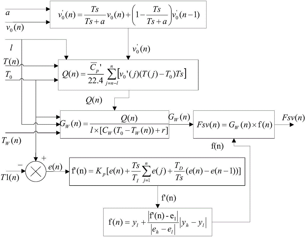
[0122] Such as figure 2 As shown, the combined structure diagram of the temperature control model based on the time window enthalpy value integration of the four program modules, in the figure,

[0123] a: Indicates the parameters used to adjust the filtering effect

[0124] v 0 (n): Indicates the measured value of flue gas flow entering the tower body, in m 3 / s

[0125] v 0 '(n): Indicates the filtered flue gas flow measurement value, the unit is m 3 / s

[0126] Q(n): Indicates the integral value of the enthalpy that should be removed within the time window, and the unit is kJ / s

[0127] f(n): Indicates...

Embodiment 2

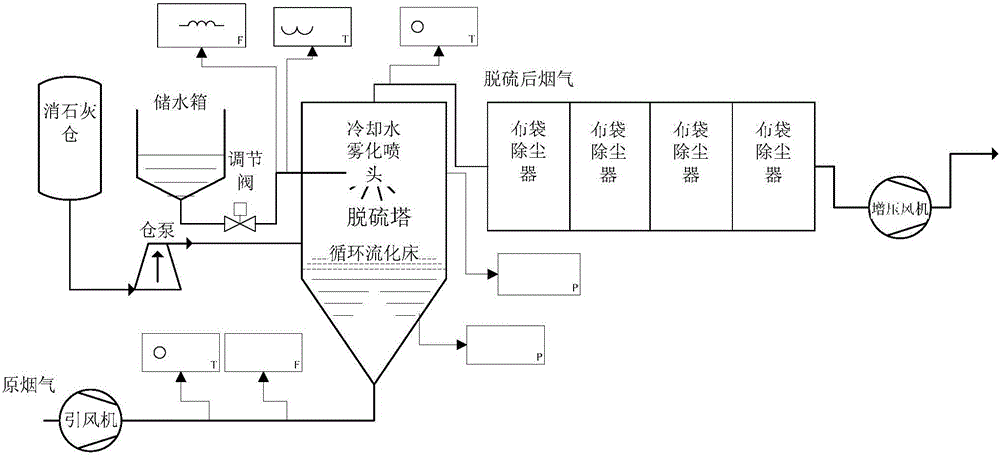
[0198] This embodiment is based on the flue gas cooling control method of time window enthalpy integration, obtains the flue gas flow rate at the inlet of the flue gas treatment system, calculates the integral value of the flue gas enthalpy that should be removed, divides the integral value by the length of the time window, and establishes the time window. The static functional relationship model between the enthalpy value to be removed per unit time and the cooling water flow rate controls the flow rate of the cooling water according to the integral of the enthalpy removal required by the flue gas.

[0199] The cooling water capacity is calculated based on the enthalpy of flue gas contained between the cooling water nozzle and the temperature detection point in the piping system, and the time taken by the flue gas in the piping system from the cooling water nozzle to the temperature detection point as the time window length .

[0200] Such as image 3 As shown, the temperatu...


PUM


Abstract

The invention discloses a time-window-enthalpy-value-integral-based smoke cooling control method and system. The method comprises: obtaining a smoke flow at an entrance of a smoke processing system; calculating an integral value of a smoke removing enthalpy; dividing the integral value by a time window length; establishing a static function relation model between the removing enthalpy value and cooling water flows in unit time in the time window; and controlling the flow of cooling water according to the integral of removing enthalpy needed by the smoke. Therefore, the cooling water flow during the smoke cooling process can be effectively controlled.

Description

technical field [0001] The invention relates to a flue gas cooling control method and system based on time window enthalpy value integration. Background technique [0002] Such as figure 1 Shown is a schematic diagram of the sintering flue gas desulfurization process. The high-temperature raw flue gas discharged from sintering enters the desulfurization tower, and in the desulfurization tower, it accelerates through the Venturi tube and forms a circulating fluidized bed with the desulfurization agent (slaked lime) added into the tower. The desulfurization reaction is mainly completed in the bed. The reaction requires the participation of water, which not only provides an ion environment for the reaction, but also provides a suitable temperature for the reaction, so atomized cooling water needs to be sprayed into the tower. The purpose of controlling the cooling water is to control the temperature. If the temperature is too high, it will affect the efficiency of the desulfu...

Claims


Application Information

Patent Timeline
Patent Type & Authority Applications(China)
IPC IPC(8): G05B13/04
Inventor 牟旭升
Owner HUATIAN ENG & TECH CORP MCC
Why Eureka
Try Eureka