Cage pocket machining device

A processing device and cage technology, which is applied in the field of bearing parts processing, can solve the problems of hidden safety hazards for workers, waste cages, and high manufacturing costs, and achieve the effects of high flexibility, high safety, and reduced manufacturing accuracy and assembly difficulty

Active Publication Date: 2015-12-09
LUOYANG BEARING RES INST CO LTD
View PDF8 Cites 12 Cited by
  • Summary
  • Abstract
  • Description
  • Claims
  • Application Information

AI Technical Summary

Problems solved by technology

[0004] However, when using this processing technology and cooperating with this kind of tooling to process the pocket holes on the cage, higher positioning accuracy requirements are required. The processing accuracy requirements for the fixed axis of the workpiece and the drilling machine are higher, and the manufacturing cost is higher. When drilling, the drill bit must be aligned with the blind hole on the small diameter section of the workpiece fixed shaft, otherwise the drill bit will not accurately extend into the blind hole and contact with the workpiece fixed shaft, resulting in chipping, causing serious work accidents and bringing great harm to the staff. At the same time, when using this processing method and tooling to process a non-metallic material cage with certain elasticity, such as an aramid-modified PTFE cage, the aramid-modified PTFE will compress the nut Under the extrusion, a large compression deformation occurs in the axial direction. When drilling is performed on the cage body in a state of compression deformation, the cage will elastically recover after the processing is completed, so that the processed pocket hole diameter becomes larger. The pocket holes cannot be used at all, and the processed cages are almost all waste products

Method used


Image

  • Cage pocket machining device

Examples


Embodiment Construction

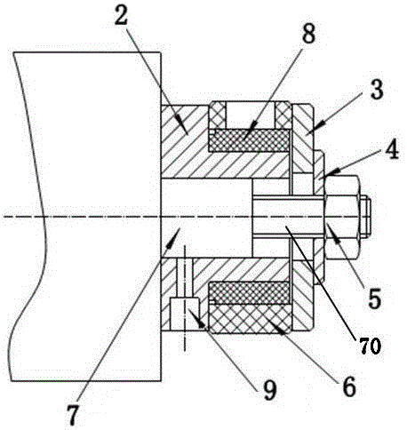
[0013] Embodiment 1 of the cage pocket processing device of the present invention: as figure 1 As shown, it includes a fixing seat, which is provided with a workpiece fixing shaft, and the workpiece fixing shaft includes a central axis 7 extending left and right, and the outer circumference of the central shaft 7 is provided with a fixing sleeve 2, and the fixing sleeve 2 is provided with radially extending screws Hole 9, the fixed sleeve 2 realizes the axial and circumferential positioning with the central axis 7 through the fastening screw in the screw hole 9, the outer circumference of the fixed sleeve 2 is a stepped outer peripheral surface with a large left end and a small right end, and the central axis 7 The right end is provided with a threaded shaft 70, and the threaded shaft 70 protrudes outward from the right end of the fixed sleeve 2, and the threaded shaft 70 is located at the position of the right end of the fixed sleeve 2 and is provided with a baffle plate 3, an...


PUM


Abstract

The invention provides a cage pocket machining device which comprises a workpiece fixing shaft. A supporting sleeve is arranged on the periphery of the workpiece fixing shaft and used for being sleeved with a cage blank so as to conduct radial supporting on the cage blank. The supporting sleeve is made of nonmetal materials and achieves circumferential locking with the workpiece fixing shaft. According to the cage pocket machining device, because the cage blank is supported through the supporting sleeve made of the nonmetal materials, the situation that a cutting edge cracks when a drill bit drills through the cage blank and makes contact with the workpiece fixing shaft is avoided in the drilling process, and safety is high. Meanwhile, the drilling position has high flexibility and is not restrained by a hole which allows a drill bit to enter and is reserved in the workpiece fixing shaft, so that the tool manufacturing precision and the assembly difficulty are reduced.

Description

technical field [0001] The invention relates to the field of bearing parts processing, in particular to a cage pocket processing device. Background technique [0002] During the development of modern rolling bearing technology, in order to improve bearing capacity, optimize bearing design, reduce bearing noise and vibration, improve bearing reliability, extend bearing service life, and reduce production costs, non-metallic materials are often used to manufacture cages. Compared with the metal material cage, the non-metallic material cage has the advantages of low density, small mass, friction and wear resistance, excellent self-lubricating performance, good shock absorption effect, corrosion resistance, etc., but due to the poor dimensional stability of non-metallic materials during processing, The thermal expansion coefficient is large and the machining accuracy is difficult to control. [0003] For example, the Chinese invention patent with application publication number ...

Claims


Application Information

Patent Timeline
Patent Type & Authority Applications(China)
IPC IPC(8): B23Q3/00
CPCB23Q3/00B23Q2703/10
Inventor 孙立才邢东红王俊峰颜容亮王利峰
Owner LUOYANG BEARING RES INST CO LTD
Why Eureka
Try Eureka