Microwave frequency conversion method and apparatus

A technology of microwave frequency conversion and wavelength division multiplexer, which is applied to electrical components, modulation transfer, demodulation, etc. It can solve the problems of high technical difficulty, unfavorable practicality, difficult frequency signal tuning, and difficult guarantee of two-wavelength laser gain equalization, etc. question

Active Publication Date: 2015-12-09
成都华光瑞芯微电子股份有限公司
View PDF7 Cites 14 Cited by
  • Summary
  • Abstract
  • Description
  • Claims
  • Application Information

AI Technical Summary

Problems solved by technology

[0003] One is to use two independent lasers to beat frequency to generate microwave signals, one of which has a fixed frequency and the other has an adjustable frequency, and uses an optical phase-locked loop to lock the phases of the two lasers, but this method is technically difficult not conducive to practical
[0004] The other is to use the same laser to generate lasers of two frequencies through related technical means, so that the microwave signal can be output directly, and the tuning of the microwave signal can be realized by changing the birefringence effect of the linear cavity fiber laser to change the frequency interval of the two lasers, but This method of applying stress to the laser fiber is random, which is not conducive to automatic control, and the whole laser is easily affected by environmental factors, it is difficult to realize the tuning of the beat frequency signal, and the gain balance of the two wavelength lasers in the cavity is not easy to guarantee

Method used


Image

  • Microwave frequency conversion method and apparatus
  • Microwave frequency conversion method and apparatus
  • Microwave frequency conversion method and apparatus

Examples


Embodiment 1

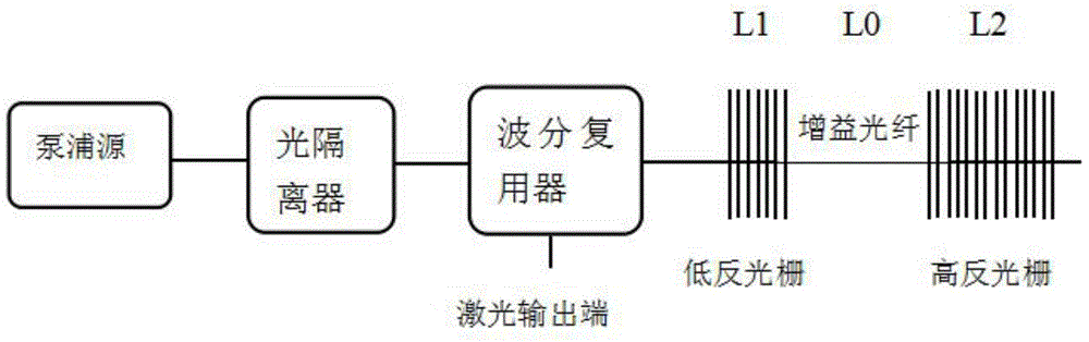
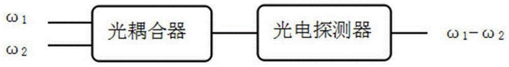
[0071] A microwave frequency conversion device in this embodiment includes a fiber laser, a polarized beam splitter, an electro-optic modulator, a polarization controller, a fiber coupler, and a photodetector, wherein the output end of the fiber laser is connected to the polarization The input end of the optical beam splitter is connected, an output end of the polarizing beam splitter is connected to an input end of the electro-optic modulator, an external microwave signal is connected to the other input end of the electro-optic modulator, and the output end of the electro-optic modulator is The end is coupled to an input end of the fiber coupler, the other output end of the polarization beam splitter is connected to the input end of the polarization controller, and the output end of the polarization controller is coupled to the other input end of the fiber coupler The output end of the optical fiber coupler is connected to the input end of the photodetector, and the output end...

Embodiment 2

[0073] A microwave frequency conversion device in this embodiment includes a fiber laser, a polarized beam splitter, an electro-optic modulator, a polarization controller, a fiber coupler, and a photodetector, wherein the output end of the fiber laser is connected to the polarization The input end of the optical beam splitter is connected, an output end of the polarizing beam splitter is connected to an input end of the electro-optic modulator, an external microwave signal is connected to the other input end of the electro-optic modulator, and the output end of the electro-optic modulator is The end is coupled to an input end of the fiber coupler, the other output end of the polarization beam splitter is connected to the input end of the polarization controller, and the output end of the polarization controller is coupled to the other input end of the fiber coupler end, the output end of the optical fiber coupler is connected to the input end of the photodetector, and the outpu...


PUM


Abstract

The invention relates to the microwave photon field, especially to a microwave frequency conversion method and apparatus. The apparatus is composed of a fiber laser, a polarizing beam splitter, an electro-optic modulator, a polarizing controller, a fiber coupler and a photoelectric detector. The fiber laser, the polarizing beam splitter, and the photoelectric detector are successively connected and then are coupled to one input terminal of the fiber coupler; the polarizing beam splitter and the polarizing controller are connected and then are coupled to the other input terminal of the fiber coupler; and the output terminal of the fiber coupler is connected with the photoelectric detector and the photoelectric detector outputs a converted frequency conversion signal. According to the invention, a microwave local oscillator signal source in the traditional frequency conversion way does not need to be provided and conversion from a broadband microwave signal to an intermediate frequency signal can be realized.

Description

Technical field: [0001] The invention relates to the field of microwave photons, in particular to a microwave frequency conversion method and device, which are mainly used in the fields of radar communication and optical radio transmission. Background technique [0002] Using optical means to generate high-quality microwave signals and integrating optical fiber transmission, high-speed optoelectronic devices and microwave signal radiation transmission in space has become the development direction of the next generation of wireless communication. Photogenerated microwave technology uses lasers, photodetectors and other devices to generate microwave signals optically. At present, the most commonly used optically generated microwave technology is the optical beat frequency method. The microwave signal generated by the optical beat frequency method mainly relies on coherent narrow linewidth lasers with two frequencies close to each other. At present, the optically generated mic...

Claims


Application Information

Patent Timeline
Patent Type & Authority Applications(China)
IPC IPC(8): H03D7/00
Inventor 罗孝均赵士勇王韧
Owner 成都华光瑞芯微电子股份有限公司
Why Eureka
Try Eureka