Electro-optic mode converter with Mach-Zehnder interferometer structure and implementing method thereof

A technology of a mode converter and an implementation method, applied in the field of optical communication, can solve the problems of slow conversion speed, complex structure, insufficient stability, etc., and achieve the effect of wide operating wavelength range and fast conversion speed

Inactive Publication Date: 2015-12-16
UNIV OF ELECTRONICS SCI & TECH OF CHINA
View PDF4 Cites 14 Cited by
  • Summary
  • Abstract
  • Description
  • Claims
  • Application Information

AI Technical Summary

Problems solved by technology

The realization of spatial light path mode conversion includes phase matching method (PhaseMatchingMethod, PMM), spatial light modulator (SpatialLightModulator, SLM), spot-based coupling method (Spot-BasedModeCoupler, SBMC), etc., based on optical fiber and planar optical waveguide mode Converters include fiber directional couplers, long-period fiber gratings, asymmetric optical waveguide couplers, asymmetric waveguide Y-branches, etc. These devices have good compatibility with existing optical fiber communication systems, but due to material limitations, they can only Provides fixed mode conversion and does not have reconfigurable features, and the reconfigurable features of devices are an important property to meet the needs of future intelligent networks
The reconfigurable mode converters reported so far include tunable mode converters driven by ultrasonic waves, long-period waveguide grating mode converters induced by the electro-optic effect, and thermo-optic mode converters based on asymmetric Mach-Zehnder interference structures of polymer materials. etc. These devices have problems such as insufficient stability, complex structure, slow switching speed and insufficient working wavelength range.

Method used


Image

  • Electro-optic mode converter with Mach-Zehnder interferometer structure and implementing method thereof
  • Electro-optic mode converter with Mach-Zehnder interferometer structure and implementing method thereof
  • Electro-optic mode converter with Mach-Zehnder interferometer structure and implementing method thereof

Examples


Embodiment 1

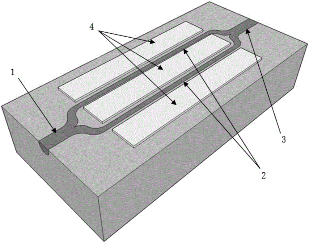
[0027] figure 1 The basic structure diagram of a new electro-optical mode converter based on the Mach-Zehnder interferometer structure realized by X-cut lithium niobate material. It mainly includes an input waveguide 1, two interference arms 2, an output waveguide 3 and an electro-optical phase modulation electrode 4.

[0028] Both input waveguide 1 and output waveguide 3 are dual-mode waveguides; input waveguide 1 and output waveguide 3 support two modes, and the LP in the fiber 01 The light wave of the mode is mainly excited in the input waveguide 1 to produce the fundamental mode, LP 11The light wave of the mode is mainly excited in the input waveguide 1 to generate the first-order mode. The two interference arms 2 are single-mode waveguides; the two interference arms 2 are symmetrical structures, one end of the input waveguide 1 and the two interference arms 2 is connected through the first Y branch waveguide, and the other end of the output waveguide 3 and the two inter...

Embodiment 2

[0034] Figure 4 The basic structure diagram of a new electro-optical mode converter based on the Mach-Zehnder interferometer structure realized by Z-cut lithium niobate material. It mainly includes an input waveguide 1, two interference arms 2, an output waveguide 3 and an electro-optical phase modulation electrode 4.

[0035] Both input waveguide 1 and output waveguide 3 are dual-mode waveguides; input waveguide 1 and output waveguide 3 support two modes, and the LP in the fiber 01 The light wave of the mode is mainly excited in the input waveguide 1 to produce the fundamental mode, LP 11 The light wave of the mode is mainly excited in the input waveguide 1 to generate the first-order mode. The two interference arms 2 are single-mode waveguides; the two interference arms 2 are symmetrical structures, one end of the input waveguide 1 and the two interference arms 2 is connected through the first Y branch waveguide, and the other end of the output waveguide 3 and the two int...

Embodiment 3

[0039] Figure 5 The basic structure diagram of the new electro-optic mode converter based on the Mach-Zehnder interferometer structure realized by the electro-optic polymer material. The core layer of the electro-optic polymer is amorphouspolycarbonateEOmaterial, and the cladding is su8; the Mach-Zehnder interferometer structure mainly includes an input waveguide 1, two interference arms 2, an output waveguide 3 and an electro-optic phase modulation electrode 4.

[0040] Both input waveguide 1 and output waveguide 3 are dual-mode waveguides; input waveguide 1 and output waveguide 3 support two modes, and the LP in the fiber 01 The light wave of the mode is mainly excited in the input waveguide 1 to produce the fundamental mode, LP 11 The light wave of the mode is mainly excited in the input waveguide 1 to generate the first-order mode. The two interference arms 2 are single-mode waveguides; the two interference arms 2 are symmetrical structures, one end of the input wavegui...


PUM


Abstract

The invention relates to optical communication field and provides an electro-optic mode converter with a Mach-Zehnder interferometer structure and an implementing method thereof. The electro-optic mode converter comprises the Mach-Zehnder interferometer structure and an electro-optic phase modulating electrode, is mainly based on an electro-optic effect and an interference principle, and changes a phase relation of light waves on two interference arms by controlling voltage applied to the electro-optic phase modulating electrode, thereby achieving conversion between two modes. The electro-optic mode converter is fast in mode conversion speed, wide in operating bandwidth, and has practical application value.

Description

technical field [0001] The invention relates to the field of optical communication, in particular to a novel electro-optic mode converter with a Mach-Zehnder interferometer structure with fast mode conversion speed and wide wavelength range and its realization method. Background technique [0002] With the rapid growth of services such as the Internet and mobile Internet, the future communication network needs to continuously increase the transmission capacity to meet people's growing demand for information. With the application of technologies such as dense wavelength division multiplexing (DenseWavelengthDivisionMultiplex, DWDM), polarization state multiplexing (PolarizationDivisionMultiplex, PDM) and orthogonal frequency division multiplexing (OpticalFrequencyDivisionMultiplex, OFDM), the transmission capacity of optical communication systems based on single-mode fiber has been Near the Shannon limit of nonlinear optical fiber, the optical communication system will face a...

Claims


Application Information

Patent Timeline
Patent Type & Authority Applications(China)
IPC IPC(8): G02B6/14
Inventor 陈开鑫张梦若郑建成王玲芳
Owner UNIV OF ELECTRONICS SCI & TECH OF CHINA
Why Eureka
Try Eureka