
Multi-pole drive power supply for ultraviolet (UV) lamp

A pole drive and power supply technology, applied in the field of power supply, can solve the problems of increased cathode loss, failure to light up, large heat generation, etc., and achieve the effects of reducing volume and weight, increasing power density, and prolonging service life

Inactive Publication Date: 2015-12-23
SHENZHEN TONGYU ELECTRICAL APPLIANCE CO LTD
View PDF7 Cites 6 Cited by
  • Summary
  • Abstract
  • Description
  • Claims
  • Application Information

AI Technical Summary

Problems solved by technology

The disadvantages of this method are: large volume, low efficiency, high heat generation, low ratio of UV lamps converting electrical energy into effective ultraviolet rays, and unstable ultraviolet intensity emitted by UV lamps;
[0003] The existing UV power supply can only adjust the power gear by connecting a power frequency transformer in parallel. It is difficult to achieve the power adjustment that is really needed. Fluctuation affects the use effect. The transmission of power frequency transformer energy is completely open-loop transmission. For example, the input is 380AC, the transformation ratio is 1:2, and the output is 760VAC. If the input becomes 320VAC, the output is 640VAC, which leads to UV The ultraviolet energy output of the lamp tube will decrease and fail to meet the requirements. If the input voltage increases at this time, the ultraviolet energy output of the UV lamp tube will increase or even burst the tube;
[0004] The energy of the existing UV power supply is determined according to the input voltage when it is started, especially at the peak of the AC voltage, the current is quite large, which is 1.414 times the effective value, which has a serious impact on the life of the lamp. Greatly shorten the service life of the lamp;
[0005] The existing UV power supply requires a separate ignition circuit to achieve ignition. The UV lamp can only work normally after the ignition is successful, but the general ignition circuit uses high voltage and low current, and the starting peak voltage used is higher. , the value is 4.0-5.0kV, which is much higher than the required start-up voltage. When a new lamp is ignited, the cathode sputtering is very severe, the cathode loss is intensified, and the breakdown voltage value increases rapidly.
The defect of this ignition method is that when the UV lamp and the metal halide lamp have not entered the later stage of life, they cannot be lit due to cathode damage, which greatly affects the service life of the UV lamp.

Method used


Image

  • Multi-pole drive power supply for ultraviolet (UV) lamp
  • Multi-pole drive power supply for ultraviolet (UV) lamp
  • Multi-pole drive power supply for ultraviolet (UV) lamp

Examples


specific Embodiment 2

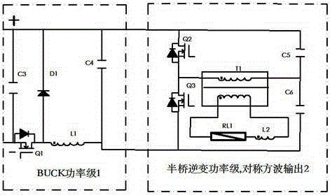
[0041] refer to figure 2 As shown, a UV lamp multi-stage drive power supply includes a BUCK power regulation circuit 1 and a symmetrical half-bridge inverter circuit 2, wherein the BUCK power regulation circuit 1 includes a MOSFET switch tube Q1, a freewheeling diode D1, and an energy storage filter inductor L1. The input capacitor C3 is connected between the input positive and negative bus bars, and the output capacitor C4 is connected between the output positive bus bar and the negative bus bar; the symmetrical half-bridge inverter circuit 2 includes switching tubes Q2, Q3, capacitors C5, C6, and an output transformer. T1, current limiting inductor L2. The drain of MOSFET switch Q2 and one end of capacitor C5 are connected to the output positive bus of the BUCK circuit, the source of switch Q3 and one end of capacitor C6 are connected to the output negative bus of the BUCK circuit, and the transformer T1 One end of the primary side is connected to the source of MOSFET swit...

specific Embodiment 3

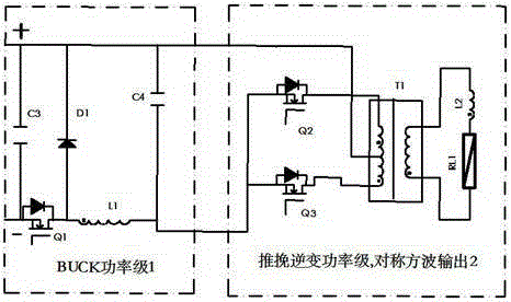
[0043] refer to image 3 As shown, a UV lamp multi-stage drive power supply includes a BUCK power regulation circuit 1 and a push-pull bridge inverter circuit 2 . The BUCK power regulation circuit 1 includes a MOSFET switch tube Q1, a freewheeling diode D1, an energy storage filter inductor L1, an input capacitor C3 connected between the input positive and negative bus bars, and an output capacitor C4 connected between the output positive bus bar and the negative bus bar The push-pull bridge inverter circuit 2 includes MOSFET switch tubes Q2, Q3, output transformer T1, and current-limiting inductor L2; the sources of the MOSFET switch tubes Q2 and Q3 of the push-pull bridge inverter circuit are connected to the output negative of the BUCK circuit at the same time On the bus, the two ends of the primary side of the transformer T1 are respectively connected to the drains of the MOSFET switch tubes Q2 and Q3, the neutral tap of the primary side of the transformer T1 is connected ...

specific Embodiment 4

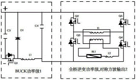
[0046] refer to Figure 4 As shown, a UV lamp multi-level drive power supply, including BUCK power regulation circuit 1, asymmetrical half-bridge inverter circuit 2; wherein BUCK power regulation circuit 1 includes MOSFET switch tube Q1, freewheeling diode D1, energy storage filter inductor L1 , the input capacitor C3 is connected between the input positive and negative bus bars, and the output capacitor C4 is connected between the output positive bus bar and the negative bus bar; the asymmetrical half-bridge inverter circuit 2 includes MOSFET switch tubes Q2 and Q3, and an output transformer T1, Current limiting inductor L2. The drain of the MOSFET switch Q2 is connected to the output positive bus of the BUCK circuit, the source of the MOSFET switch Q3 is connected to the output negative bus of the BUCK circuit, and one end of the primary side of the transformer T1 is connected to the source of the MOSFET Q2 and the MOSFET switch The drain of the tube Q3, the other end of th...


PUM


Abstract

The invention discloses a multi-pole drive power supply for an ultraviolet (UV) lamp. The multi-pole drive power supply comprises a BUCK power stage circuit or a BUCK power stage derivative circuit and a high-frequency inverting square-wave output stage circuit, which are sequentially connected with each other step by step, wherein the BUCK power stage circuit or the BUCK power stage derivative circuit comprises a switch tube Q1, a fly-wheel diode D1, a filtering energy-storage inductor L1, an input capacitor C3 and an output capacitor C4; and the high-frequency inverting square-wave output stage circuit comprises metal-oxide-semiconductor field effect transistor (MOSFET) switches Q2 to Q5, a main transformer T1 and a current-limiting inductor L2. A current soft-starting technology is adopted by the technology of lightening a lamp tube; and damages to the UV lamp tube caused by heavy current when an existing UV power supply lightens the lamp tube are avoided; and the service lifetime of the lamp tube is greatly prolonged.

Description

technical field [0001] The invention relates to the field of power supplies, in particular to a multi-stage drive power supply for UV lamps. Background technique [0002] The power supply mode of the existing UV power supply is to use a power frequency transformer to connect a large capacitor in series to adjust the output mode of the UV lamp. The disadvantages of this method are: large volume, low efficiency, high heat generation, low ratio of UV lamps converting electrical energy into effective ultraviolet rays, and unstable ultraviolet intensity emitted by UV lamps; [0003] The existing UV power supply can only adjust the power gear by connecting a power frequency transformer in parallel. It is difficult to achieve the power adjustment that is really needed. Fluctuation affects the use effect. The transmission of power frequency transformer energy is completely open-loop transmission. For example, the input is 380AC, the transformation ratio is 1:2, and the output is 76...

Claims


Application Information

Patent Timeline
IPC IPC(8): H02M7/5387H02M7/519H05B37/02
Inventor 吴金鹏王丽霞
Owner SHENZHEN TONGYU ELECTRICAL APPLIANCE CO LTD
Learn More