Biological nitrogen removal technology implemented under low temperature and low carbon source conditions
A biological denitrification and process technology, applied in the direction of biological water/sewage treatment, aerobic and anaerobic process treatment, water pollutants, etc., can solve the problems that do not conform to the circular economy, the external temperature of the effluent water quality is greatly affected, and the long hydraulic retention time To achieve the effect of reducing the amount of excess sludge, reducing the cost of construction and maintaining the concentration of sludge
- Summary
- Abstract
- Description
- Claims
- Application Information
AI Technical Summary
Problems solved by technology
Method used
Image

Examples
Embodiment 1
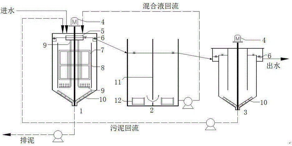
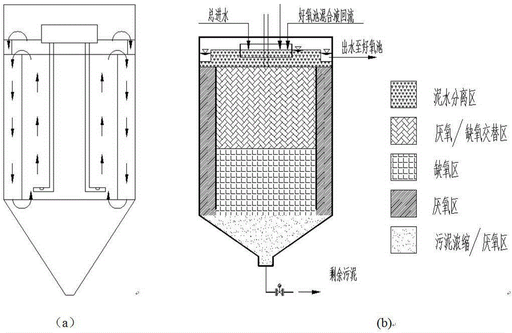
[0022] The sewage treatment system used in this embodiment is as figure 1 shown. It is composed of UAAR, nitrification tank and sedimentation tank in series. The nitrification tank and the sedimentation tank are respectively equipped with mixed liquor and sludge return devices, and the incoming water, reflux mixed liquor, and returned sludge all enter the reactor from the top of the UAAR through the diversion pipe. UAAR is equipped with a ring-mounted partition to divide it into inner and outer layers. The diversion pipe guides the mixed liquid into the bottom of the inner layer. The water flows from bottom to top in the inner layer, flows to the outer layer, flows into the inner layer from top to bottom, and continues to circulate. At the same time, there is a stirring paddle inside the inner layer to fully mix the water flow in the inner layer. The effluent from UAAR enters the nitrification tank through the overflow, and the water flows through the nitrification tank firs...
Embodiment 2
[0028] The sewage treatment system used in this embodiment is as figure 1 As shown, the effluent of the grit chamber of a sewage plant in the south is used as the water inflow of the small test device, and the return sludge of the secondary settling tank of the sewage plant is used as the inoculation sludge. The operating time is from December to March in winter. The average temperature of the environment where the small test device is located is 13.5°C, and the average water temperature is 11.5°C. And water BOD 5 / TKN<4, belongs to low carbon nitrogen ratio sewage.
[0029] After 30 days of start-up period, the denitrification process can reach a stable operation state. In this example, the mixed liquor reflux ratio is 200%, and the sludge reflux ratio is 100%. Sewage enters the following working sections in turn:
[0030] (1) UAAR: MLSS gradually increases from top to bottom, ranging from 3000 to 15000mg / L; the hydraulic retention time is 6h, and the solid retention time...
Embodiment 3
[0035] The sewage of a pig farm in the south was used as the water for the small test device. The concentration of ammonia nitrogen in the sewage reaches 500~1000mg / L, and the influent BOD 5 / TKN<4, belongs to low carbon nitrogen ratio sewage.
[0036] The sewage treatment system used in this embodiment is as figure 1 shown. The hydraulic retention time of sewage is 28h, and the residence time in UAAR and nitrification tank are 12h and 16h respectively. The reflux ratio of the mixed liquid in the nitrification tank is 600%, and the reflux ratio of the sludge in the sedimentation tank is 100%. Under this working condition, the COD removal rate can reach more than 90%, the effluent COD concentration is lower than 400mg / L, and the BOD5 concentration is lower than 50mg / L. The average removal rate of ammonia nitrogen is 93.4%, and the average concentration of effluent is less than 50mg / L. In the case of no external carbon source, the removal rate of total nitrogen reaches 70%....
PUM
 Abstract
Description
Claims
Application Information
 - R&D
- Intellectual Property
- Life Sciences
- Materials
- Tech Scout
- Unparalleled Data Quality
- Higher Quality Content
- 60% Fewer Hallucinations
Browse by: Latest US Patents, China's latest patents, Technical Efficacy Thesaurus, Application Domain, Technology Topic, Popular Technical Reports.
© 2025 PatSnap. All rights reserved.Legal|Privacy policy|Modern Slavery Act Transparency Statement|Sitemap|About US| Contact US: help@patsnap.com