A Method for Controlling Electrodeformation Orientation of Ferroelectric Single Crystal

A ferroelectric single crystal and electro-deformation technology, which is applied in the field of ferroelectric materials, can solve the problems of practical inconvenience and achieve the effect of increasing the ratio, multiple control methods, and increasing the probability of occurrence

Active Publication Date: 2017-12-22
UNIV OF SCI & TECH OF CHINA
View PDF9 Cites 0 Cited by
  • Summary
  • Abstract
  • Description
  • Claims
  • Application Information

AI Technical Summary

Problems solved by technology

However, the operating voltage of this control method is limited in a very narrow range, which is very inconvenient for practical use; more importantly, the direction of the strain in the 90-degree rotation in the plane is also uncertain in advance.

Method used


Image

  • A Method for Controlling Electrodeformation Orientation of Ferroelectric Single Crystal
  • A Method for Controlling Electrodeformation Orientation of Ferroelectric Single Crystal
  • A Method for Controlling Electrodeformation Orientation of Ferroelectric Single Crystal

Examples


Embodiment 1

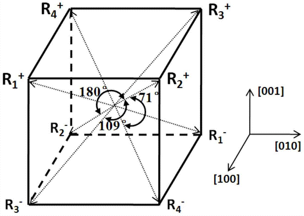
[0050] ①, figure 2 A schematic diagram of the spontaneous polarization direction in the (001) orientation PMN-0.25PT trigonal ferroelectric single crystal selected for use in Example 1 of the present invention, as figure 2 As shown, the trigonal lead magnesium niobate titanate Pb(Mg 1 / 3 Nb 2 / 3 ) 0.75 Ti 0.25 o 3 (abbreviated as PMN-0.25PT) is a representative of the tripartite ferroelectric single crystal, and its surface is the (001) crystal plane.

[0051] ②. The (001) plane of the PMN-0.25PT single crystal selected in ① is beveled in one direction along the [010] direction, and the bevel angle is 14 degrees, and the beveled single crystal is obtained, as shown in image 3 as shown, image 3 It is a schematic diagram of a single-crystal (001) PMN-0.25PT ferroelectric in Example 1 of the present invention after being bevelled in one direction.

[0052] The chamfered PMN-0.25PT single crystal was subjected to conventional double-sided polishing and cutting, and the si...

Embodiment 2

[0058] ①. The (001) plane of the selected PMN-0.25PT single crystal is obliquely cut in both directions, that is, it is first beveled along the [010] direction by 14 degrees, and then beveled by 1.5 degrees along the [100] direction to obtain the beveled single crystal, such as Figure 7 as shown, Figure 7 It is a schematic diagram of a single crystal (001) PMN-0.25PT ferroelectric in Example 2 of the present invention after bidirectional beveling is performed.

[0059]The chamfered PMN-0.25PT single crystal was subjected to conventional double-sided polishing and cutting, and the size of the obtained test sample was 5mm*5mm*0.5mm.

[0060] ②. For the obliquely cut PMN-0.25PT single crystal test sample after ① polishing, the upper electrode layer is evaporated on both sides, such as Figure 8 shown, Figure 8 It is a schematic diagram of the PMN-0.25PT ferroelectric with two-way chamfering in Example 2 of the present invention after two electrodes are plated. Among them, ...


PUM


Abstract

The present application provides a method for controlling the electro-strain orientation of a ferroelectric single crystal. The trigonal ferroelectric single crystal (001) surface is obliquely cut to obtain the obliquely cut single crystal; the obliquely cut single crystal is placed on the The initial polarization is performed under an external electric field, and then the polarization is performed under an external reverse electric field to obtain a reversely polarized single crystal. This application uses oblique cutting to process the (001) surface of the trigonal ferroelectric single crystal, so that the surface of the single crystal is no longer in a strict (001) orientation; in this way, when the electric field is reversed up and down, the ratio of 109° polarization reversal will increase . The present invention implements a simple oblique cutting process on (001) oriented trigonal ferroelectric single crystal, so that the surface normal does not coincide with the crystal axis, destroys the symmetry of the spontaneous polarization direction around the surface normal, and improves the 109-degree polarization reversal. Occurrence probability, so as to realize the control of the electrostrain orientation. In the present invention, heating-assisted polarization is preferred, and a single 109-degree domain switching path can be realized, which is beneficial to strain control applications such as magnetic thin film / piezoelectric single crystal heterojunction.

Description

technical field [0001] The present invention relates to the technical field of ferroelectric materials, in particular to a method for controlling the orientation of ferroelectric single crystal induced deformation. Background technique [0002] Some crystals have spontaneous polarization in a certain temperature range, and the direction of their spontaneous polarization can be reversed with the reverse of the direction of the external electric field. This property is called ferroelectricity, and the crystal with ferroelectricity is called ferroelectricity. body (or ferroelectric material, ferroelectric material). Ferroelectric materials have a wide range of applications in energy conversion and information storage due to their nonvolatile ferroelectric polarization and piezoelectric / inverse piezoelectric effects. In recent years, the study of thin film strain control and the rise of composite magnetoelectric materials have brought important potential scenarios for the appli...

Claims


Application Information

Patent Timeline
Patent Type & Authority Patents(China)
IPC IPC(8): C30B33/04B28D5/00
Inventor 罗震林赵江涛何浩杨远俊高琛
Owner UNIV OF SCI & TECH OF CHINA
Why Eureka
Try Eureka