Cutting blade with improved coating structure and manufacturing method of cutting blade

A cutting insert and coating technology, applied in coating, turning equipment, tools for lathes, etc., can solve the problems of coating uniformity decline, performance decline, edge chipping, etc., to reduce cutting force and cutting heat, improve anti-oxidation performance, good effect of anti-wear performance

Active Publication Date: 2016-01-27
ZHUZHOU CEMENTED CARBIDE CUTTING TOOLS CO LTD
View PDF8 Cites 11 Cited by
  • Summary
  • Abstract
  • Description
  • Claims
  • Application Information

AI Technical Summary

Problems solved by technology

CN103171178A Chinese patent document discloses a cutting tool with improved transition layer structure, the transition layer consists of two layers of TiC with different compositions x N y o z and 1 layer of TiAlC x3 N y3 o z3 Composite, the thickness is very small, can refine the outer layer α-Al 2 o 3 grain of the coating while improving the outer layer of α-Al 2 o 3 The bonding performance of the coating, the optimization of this transition layer improves the TiCN/Al 2 o 3 The bonding strength of the interface can improve the anti-stripping performance of the coating, but due to the existence of residual stress and thermal cracks, the strength of the CVD-coated insert has not been improved. In the middle, it is prone to edge chipping and failure
CN101219591A Chinese patent document discloses a CVD-coated insert for shallow hole drilling with high toughness requirements. The coating includes: TiC x N y o z The first (innermost) layer, thickness x N y o z layer with a thickness of 1 μm to 8 μm, with columnar grains; fine-grained grains К-Al 2 o 3 layer, thickness 0.5 μm to 5 μm, and additional TiC thickness x N y o z layer, at the rake face, completely or partially provided wi

Method used


Image

  • Cutting blade with improved coating structure and manufacturing method of cutting blade
  • Cutting blade with improved coating structure and manufacturing method of cutting blade
  • Cutting blade with improved coating structure and manufacturing method of cutting blade

Examples


Embodiment 1

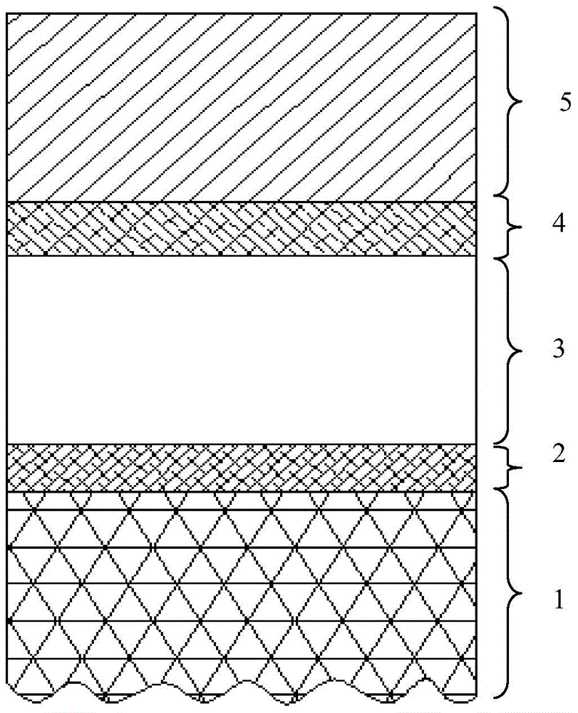
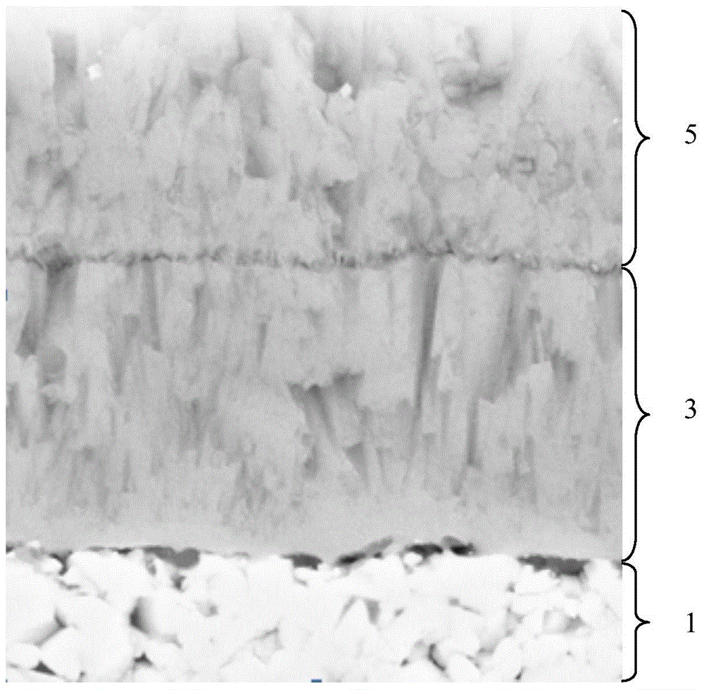
[0043] A cutting insert with improved coating structure of the present invention comprises a substrate A1 and a coating deposited on the substrate A1. The matrix A1 is cemented carbide, and its composition is 10wt% Co, 1wt% Ti and Ta cubic carbonitride, and the rest WC powder. Coating includes inner layer C3 as TiC x N y o z layer and the outer layer D5 is (Ti a Al b )(C i N j o k ) layer, in this embodiment, x=0.4, y=0.5, z=0.1, a=0.46, b=0.013, i=0.197, j=0.13, k=0.20, therefore, the inner layer C3 is TiC 0.4 N 0.5 o 0.1 layer, the outer layer D5 is (Ti 0.46 Al 0.013 )(C 0.197 N 0.13 o 0.20 )layer. The inner layer C3 has a thickness of 5 μm and has a face-centered cubic structure, and the outer layer D5 has a thickness of 5 μm and has a face-centered cubic structure. After the surface treatment of the outer layer D5, the surface residual stress δ is -1350MPa, and the surface roughness Ra on the length of 300μm is 0.18μm.

[0044] A method for preparing a cut...

Embodiment 2

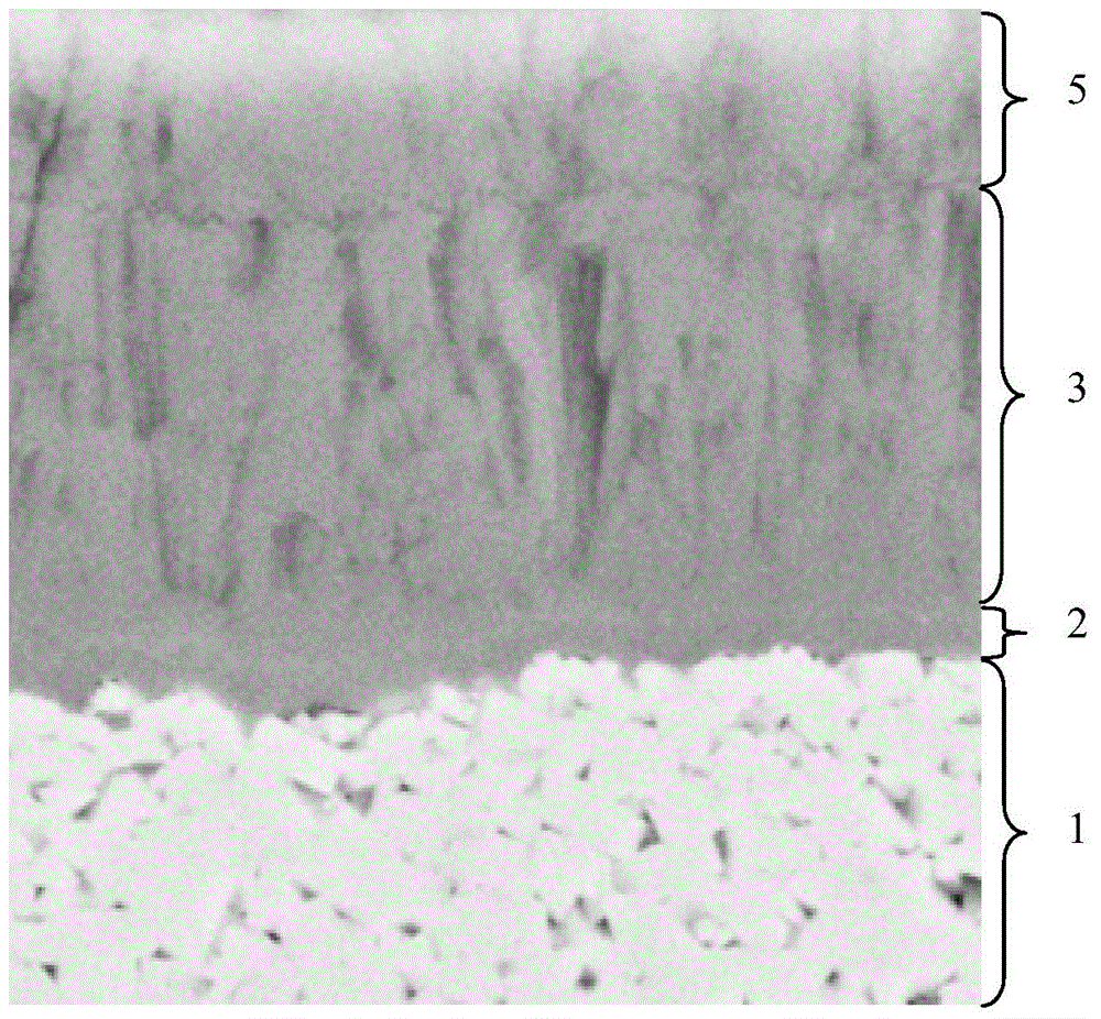
[0055] A cutting insert with improved coating structure of the present invention comprises a substrate A1 and a coating deposited on the substrate A1. The substrate A1 is cemented carbide, and its composition is the same as that of the substrate A1 in Example 1. The coating includes transition layer B2 as TiN layer and inner layer C3 as TiC x N y o z layer and the outer layer D5 is (Ti a al b )(C i N j o k ) layer, in this embodiment x=0.55, y=0.4, z=0.05, a=0.44, b=0.002, i=0.13, j=0.35, k=0.078, therefore, the inner layer C3 is TiC 0.55 N 0.4 o 0.05 layer, the outer layer D5 is (Ti 0.44 al 0.002 )(C 0.13 N 0.35 o 0.078 )layer. The inner layer C3 has a thickness of 5 μm and has a face-centered cubic structure; the outer layer D5 has a thickness of 2 μm and has a face-centered cubic structure. The transition layer B2 is TiN, which has a cubic crystal structure. The transition layer B2 mainly plays the role of optimizing the structure and improving the nucleation...

Embodiment 3

[0065] A cutting insert with improved coating structure of the present invention comprises a substrate A1 and a coating deposited on the substrate A1, the substrate A1 is cemented carbide, its composition is 8wt% Co, and the balance is WC powder. Coating includes inner layer C3 as TiC x N y o z layer, the outer layer D5 is (Ti a al b )(C i N j o k ) layer and the transition layer E4 between the inner layer C3 and the outer layer D5, in this embodiment, x=0.4, y=0.6, z=0, a=0.42, b=0.01, i=0.15, j=0.17, k=0.25, therefore, the inner layer C3 is TiC 0.4 N 0.6 layer, the outer layer D5 is (Ti 0.42 al 0.01 )(C 0.15 N 0.17 o 0.25 ) layer, and the transition layer E4 is TiCO coating. The inner layer C3 has a thickness of 6 μm and has a face-centered cubic structure; the outer layer D5 has a thickness of 1.8 μm and has a face-centered cubic structure. The transition layer E4 is a TiCO coating with a cubic crystal structure. The transition layer E4 mainly plays the role ...


PUM

PropertyMeasurementUnit
Thicknessaaaaaaaaaa
Surface roughnessaaaaaaaaaa

Abstract

The invention discloses a cutting blade with an improved coating structure and a manufacturing method of the cutting blade. The cutting blade comprises a matrix A and a coating deposited on the matrix A. The coating is a multi-layer coating and at least comprises an inner layer C and an outer layer D. The inner layer C is composed of carbon-nitrogen oxide of transition elements of the IV B group or carbonitride of transition elements of the IV B group. The outer layer D is a (TiaAlb)(CiNjOk) layer, the thickness of the outer layer D is 1-20 [mu]m. Both the inner layer C and the outer layer D are of face-centered cubic structures. The manufacturing method comprises the steps of manufacturing the matrix A, selectively depositing a transition layer B, depositing the inner layer C, selectively depositing a transition layer E, depositing the outer layer D, and conducting surface treatment. The cutting blade is good in tenacity, abrasion resistance and oxidation resistance, the cutting blade has excellent cutting performance in machining of materials such as steel and stainless steel, and the manufacturing method is simple, convenient to implement, and easy to operate and control.

Description

technical field [0001] The invention belongs to the field of metal cutting, in particular to a cutting blade with improved coating structure and a preparation method thereof. Background technique [0002] Coated inserts or knives are widely used in machining in various industries such as automobiles, aviation, and microelectronics. The processing materials include steel, stainless steel, die steel, copper, aluminum and other metal materials, as well as various alloys, ceramics or composite materials. During the machining process, there are two failure mechanisms for coated tools: wear and breakage. Blade wear mainly includes abrasive wear, adhesive wear, diffusion wear and oxidation wear. Under different cutting conditions, when processing workpieces of different materials, the main cause of wear may be one or more of them. Generally speaking, when the cutting temperature is low, abrasive wear is the main one, and when the cutting temperature is high, it is mainly adhesive...

Claims


Application Information

Patent Timeline
IPC IPC(8): B23B27/00B23P15/28C23C16/30C23C16/36
Inventor 刘王平陈响明周文豪
Owner ZHUZHOU CEMENTED CARBIDE CUTTING TOOLS CO LTD
Why Eureka
Try Eureka