Manufacturing method of epoxy resin pipeline

A manufacturing method and epoxy resin technology, which can be applied to devices for coating liquid on surfaces, pretreatment surfaces, coatings, etc. The effect of avoiding gun chatter, high powder utilization, and reducing floor space

Active Publication Date: 2016-03-16
青岛豪德博尔实业有限公司
View PDF3 Cites 9 Cited by
  • Summary
  • Abstract
  • Description
  • Claims
  • Application Information

AI Technical Summary

Problems solved by technology

However, the defects are as follows: 1. The steel pipe is fixed, resulting in uneven outer spraying, that is, the bottom spraying layer is thin. 2. The inner and outer spray guns move from one side to the other side, and then reset; then the next steel pipe can be sprayed. The efficiency is not high, and the powder recycling is insufficient, and the waste of plastic coating powder is serious
3. The movable support is pulled by the steel wire. The defects are as follows. The support is located in the pipe, which is easy to cause scratches on the spraying position. 4. The steel wire rope traction makes the movable support difficult to operate when it is taken out of the pipe end or placed at the starting position of the other end.
5. There are many problems in synchronous heating and curing, because the electromagnetic heating cylinder cannot cover the whole pipeline, and the electromagnetic heating cylinder is constantly moving, resulting in uneven heating and poor curing effect
[0005] In order to solve the above technical problems, some rigid spray guns have appeared on the market, that is, the spray gun is erected at the end of the steel pipe, the spray gun is pushed forward by the moving trolley, and the track is laid under the moving trolley. However, the length of the spray gun is too long when moving from one end of the pipe to the other end. It leads to vibration at the end and uneven powder spraying. Moreover, the excessively long pipeline will inevitably increase the track distance of the moving trolley supporting the spray gun, increase the occupied area, and greatly reduce the utilization rate of the plant area.
However, reducing the length of the rigid spray gun can not solve the long pipeline (such as more than 8 meters) spraying

Method used


Image

  • Manufacturing method of epoxy resin pipeline
  • Manufacturing method of epoxy resin pipeline
  • Manufacturing method of epoxy resin pipeline

Examples


Embodiment Construction

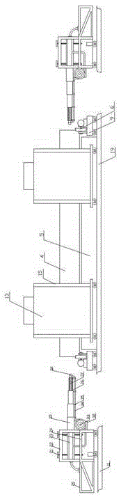
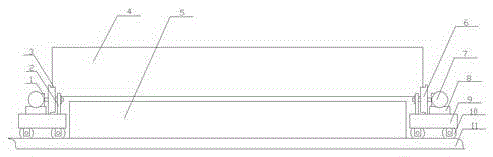
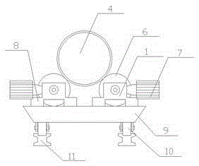
[0040] The present invention will be described below in conjunction with the accompanying drawings. Such as Figure 1-Figure 9 as shown, figure 1 It is a structural schematic diagram of the electrostatic spraying line of the present invention. figure 2 It is a structural schematic diagram of the steel pipe conveying device of the present invention. image 3 for figure 2 side view. Figure 4 It is a structural schematic diagram of the external spraying device of the present invention during operation. Figure 5 It is a structural schematic diagram of the walking box of the inner spray gun of the present invention. Image 6 It is a structural schematic diagram of the sling of the present invention. Figure 7 It is a schematic cross-sectional view of the fixing rod of the present invention. Figure 8 It is a schematic top view of the powder receiving tank of the present invention. Figure 9 It is a schematic diagram of the state of recovered powder in the powder receivi...


PUM


Abstract

The invention discloses a manufacturing method of an epoxy resin pipeline. The manufacturing method of the epoxy resin pipeline comprises the following steps that A, a steel pipe is put into a pickling tank to be subjected to acid pickling and rust removal; B, the steel pipe subjected to acid pickling is washed through clear water and dried for later use; C, intermediate-frequency heating is conducted on the steel pipe obtained in the step B; D, epoxy resin powder is sprayed to the interior and the exterior of the steel pipe synchronously through an electrostatic spraying method; E, heating and curing are conducted; and F, natural cooling is conducted, plastic coating work is conducted through an electrostatic spraying line in the step D, the electrostatic spraying line comprises a steel pipe conveying device, an outer spraying, an inner spraying device and a powder recovery device, and an extension pipe which is arranged on the inner spraying device and used for being connected with an inner spraying gun is of a hydraulic-driven telescopic structure. The manufacturing method of the epoxy resin pipeline is simple; using is convenient, the occupied area of a production line can be reduced, production efficiency is improved, vibration of the spraying gun can be avoided, powder spraying is even, and the powder utilization rate is high.

Description

Technical field: [0001] The invention relates to the technical field of pipelines, in particular to a method for manufacturing epoxy resin pipelines. Background technique: [0002] The coated pipes of steel pipes include galvanized pipes, aluminum-plated pipes, chrome-plated pipes, aluminized pipes and steel pipes with other alloy layers. Coated tubes include outer coated tubes, inner coated tubes, and inner and outer coated tubes. Commonly used coatings include plastics, epoxy resins, coal tar epoxy resins, and various glass-type anti-corrosion coating materials. The coated steel pipe is made by coating plastic on the inner wall (or outer wall if necessary) by powder fusion spraying technology, and its performance is excellent. Compared with galvanized pipe, it has the advantages of anti-corrosion, no rust, no fouling, smooth and smooth, clean and non-toxic, and long service life. According to tests, the service life of the steel-plastic composite pipe is more than thr...

Claims


Application Information

Patent Timeline
Patent Type & Authority Applications(China)
IPC IPC(8): B05D3/10B05D3/02B05D1/06
CPCB05D1/06B05D3/02B05D3/10B05D2202/00B05D2254/06
Inventor 付希波
Owner 青岛豪德博尔实业有限公司
Why Eureka
Try Eureka