Friction stir welding additive manufacture method of bar material

A technology of friction stir welding and additive manufacturing, applied in the field of manufacturing bars, can solve problems such as cracks and large deformation, and achieve the effects of excellent performance, reduced heat input, and improved overall mechanical properties

Active Publication Date: 2016-03-16
HARBIN INST OF TECH
View PDF11 Cites 31 Cited by
  • Summary
  • Abstract
  • Description
  • Claims
  • Application Information

AI Technical Summary

Problems solved by technology

[0004] The purpose of the present invention is to solve the problems of air holes, cracks and large deformation in the materials manufactured

Method used


Image

  • Friction stir welding additive manufacture method of bar material

Examples


specific Embodiment approach 1

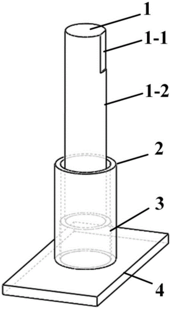
[0028] Specific implementation mode one: combine figure 1 Describe this embodiment, this embodiment is a kind of method of friction stir welding additive manufacturing bar, it comprises the following steps:

[0029] Step 1, preparation of cylindrical base metal:

[0030] First determine the type of material for additive manufacturing, and process it into a cylindrical bar 1 with a diameter of 10-50mm and a length of 50-200mm by machining; then process a deep 2- 5mm platform 1-1, the length of platform 1-1 is 10-20mm, so that the bar 1 is mechanically connected with the friction stir welding equipment through bolts; the surface of the bar 1 is polished with sandpaper, and then ultrasonicated in acetone Wash, and finally air dry for later use;

[0031] Step 2. Preparation of additive manufacturing mold:

[0032] Select a pipe with a higher melting point than the additive material to make the mold 2 for additive manufacturing, and remove oil stains and oxide films on the inner...

specific Embodiment approach 2

[0043] Specific implementation mode two: combination figure 1 To illustrate this embodiment, the material for additive manufacturing in Step 1 of this embodiment is a 2024 aluminum alloy rod. It is set in this way to ensure that the rod 1 can be clamped on the friction stir equipment and used as a material source for additive manufacturing. Other compositions and connections are the same as in the first embodiment.

specific Embodiment approach 3

[0044] Specific implementation mode three: combination figure 1 To illustrate this embodiment, in step 2 of this embodiment, a low-carbon steel pipe is selected to make the mold 2 for additive manufacturing, and the oil stains and oxide films on the inner and outer surfaces are removed. The wall thickness of the pipe is 5mm, and the inner diameter is 24mm. Such setting ensures that the mold 2 does not directly contact the high-speed rotating aluminum alloy rod 1 during the additive manufacturing process, and it can restrict the forming space of the additive metal. Other compositions and connections are the same as those in the second embodiment.


PUM

PropertyMeasurementUnit
Diameteraaaaaaaaaa
Lengthaaaaaaaaaa
Wall thicknessaaaaaaaaaa

Abstract

A friction stir welding additive manufacture method of a bar material relates to a method for manufacturing a bar material. The objective of the invention is to solve the air hole, crack and large deformation problems of the material manufactured by the existing high-energy beam additive manufacture method. The method comprises the following steps: step 1, preparing cylindrical parent metal; step 2, preparing an additive manufacture die; step 3, preparing an additive manufacture base plate; step 4, welding the die with the base plate; step 5, positioning the die and the base plate; step 6, determining additive manufacture parameters; and step 7, conducting the forming process of additive manufacture. The method is simple in manufacture technology, does not require protection gas or vacuum environment, solves air hole, crack and deformation problems easily occurring in the high-energy beam additive manufacture process, and can obtain a high-performance structural material. The method is suitable for the additive manufacture of various materials.

Description

technical field [0001] The invention relates to a method for manufacturing rods, in particular to a method for manufacturing rods by friction stir welding. Background technique [0002] Additive manufacturing technology is a technology that uses the method of gradually accumulating materials to manufacture solid parts. Compared with the traditional material removal-cutting technology, it is a "bottom-up" manufacturing method. Universities in my country have been conducting relevant research since the 1990s, but they lag behind foreign advanced levels in terms of key devices, forming materials, intelligent control and application scope, and there is still a lot of room for improvement in the direct manufacturing of high-performance terminal components. [0003] High-energy beam additive manufacturing technology using laser beams and electron beams as energy sources is an important development direction in this technology field. It has the advantages of rapid prototyping and h...

Claims


Application Information

Patent Timeline
IPC IPC(8): B23K20/12B23K20/24
CPCB23K20/122B23K20/24
Inventor 刘会杰刘向前胡琰莹曾凡勇林喆
Owner HARBIN INST OF TECH
Why Eureka
Try Eureka