Graphite depositing device for chemical vapor deposition furnace
A chemical vapor deposition and deposition device technology, which is applied in the field of graphite deposition devices for chemical vapor deposition furnaces, can solve the problems of uneven product thickness, low production efficiency, and high production costs
- Summary
- Abstract
- Description
- Claims
- Application Information
AI Technical Summary
Problems solved by technology
Method used
Image
Examples
Embodiment 1
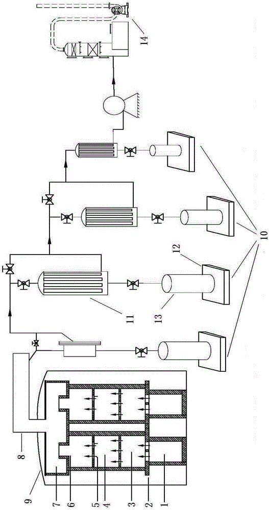
[0063] First, put solid raw materials into the graphite crucible of the solid raw material holding device, cover the crucible cover on the top, and confirm that the air flow holes on the top of the crucible cover are in good condition.
[0064] Then set the temperature rise and deposition program of the chemical vapor deposition furnace. During the deposition process, the solid raw material vapor and gas raw material are carried by the inert gas and enter the first deposition chamber through the pores. After the deposition part of the bottom cover plate of the first deposition chamber, Then enter the second deposition chamber for deposition through the gas flow holes on the partition (staggered with the gas flow holes on the cover plate), after the bottom partition plate deposition part of the second deposition chamber, finally pass through the gas flow holes on the partition (the second deposition chamber) The bottom partitions of the second deposition chamber and the gas flow...
Embodiment 2
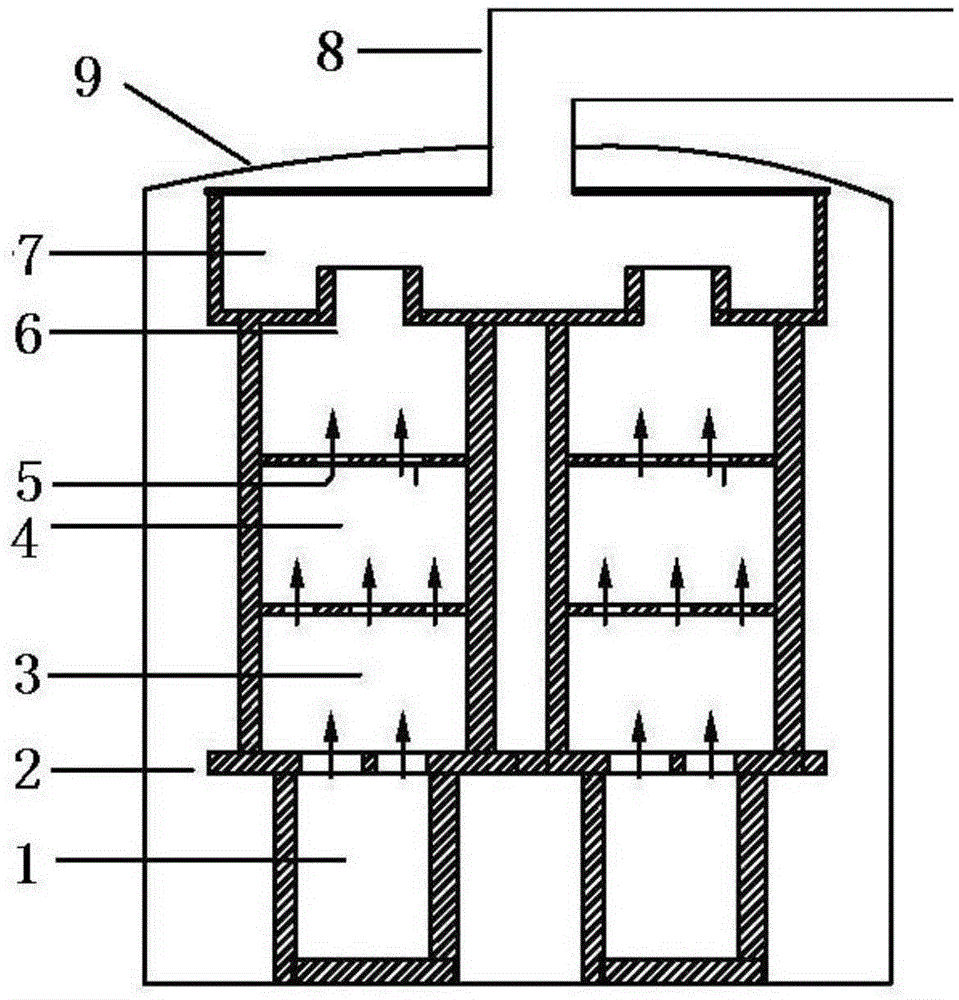
[0067] Put the zinc raw material into the graphite crucible, set the temperature rise and deposition program, during the deposition process, hydrogen selenide and zinc vapor enter the deposition chamber under the inert gas, first enter the first deposition chamber, and deposit part in the first deposition chamber , and then enter the second deposition chamber for deposition through the gas distribution plate, after the deposition part of the partition at the bottom of the second deposition chamber, enter the third deposition chamber through the gas flow holes on the partition, and deposit in the third deposition chamber. The bottom partition of the third deposition chamber. Finally, the unreacted gas and undeposited zinc selenide dust enter the dust collection room for deposition, and then enter the back-end dust multi-stage collection system and tail gas treatment system after passing through the dust guide channel into the chemical deposition process.
[0068] see figure 2...
Embodiment 3
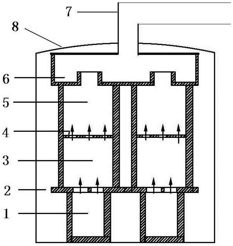
[0072] Put the zinc raw material into the graphite crucible, set the temperature rise and deposition program, during the deposition process, hydrogen sulfide and zinc vapor enter the deposition chamber under the inert gas, first enter the first deposition chamber, and deposit part in the first deposition chamber, Then enter the second deposition chamber for deposition through the gas distribution plate, and finally the unreacted gas and undeposited zinc sulfide dust enter the dust collection chamber for deposition, and enter the back-end dust multi-stage collection system after entering the chemical deposition process through the dust guide channel and exhaust treatment systems.
[0073] see image 3 , image 3 A schematic structural diagram of a graphite deposition device for a chemical vapor deposition furnace provided in Example 3 of the present invention, wherein 1 is a crucible, 2 is a crucible cover, 3 is a first deposition chamber, 4 is a partition, and 5 is a second ...
PUM
 Abstract
Description
Claims
Application Information
 - R&D
- Intellectual Property
- Life Sciences
- Materials
- Tech Scout
- Unparalleled Data Quality
- Higher Quality Content
- 60% Fewer Hallucinations
Browse by: Latest US Patents, China's latest patents, Technical Efficacy Thesaurus, Application Domain, Technology Topic, Popular Technical Reports.
© 2025 PatSnap. All rights reserved.Legal|Privacy policy|Modern Slavery Act Transparency Statement|Sitemap|About US| Contact US: help@patsnap.com


