A fixing device for deep hole drilling and welding blades

A fixing device, deep hole drilling technology, applied in auxiliary devices, welding equipment, auxiliary welding equipment, etc., can solve the problems of blade falling off or slipping, low welding quality, high rejection rate, and achieve convenient welding, high welding precision, The effect of high scrap rate

Active Publication Date: 2017-03-29
HARBIN UNIV OF SCI & TECH
View PDF5 Cites 0 Cited by
  • Summary
  • Abstract
  • Description
  • Claims
  • Application Information

AI Technical Summary

Problems solved by technology

[0004] The present invention solves the problem that the current deep hole drilling blades, guide blocks and drill bits need to be welded multiple times to complete. During the multiple welding processes, the welded blades may fall off or slip, resulting in low welding quality and resulting The problem of high scrap rate, and then propose a fixing device for deep hole drilling and welding blades

Method used


Image

  • A fixing device for deep hole drilling and welding blades
  • A fixing device for deep hole drilling and welding blades
  • A fixing device for deep hole drilling and welding blades

Examples


specific Embodiment approach 1

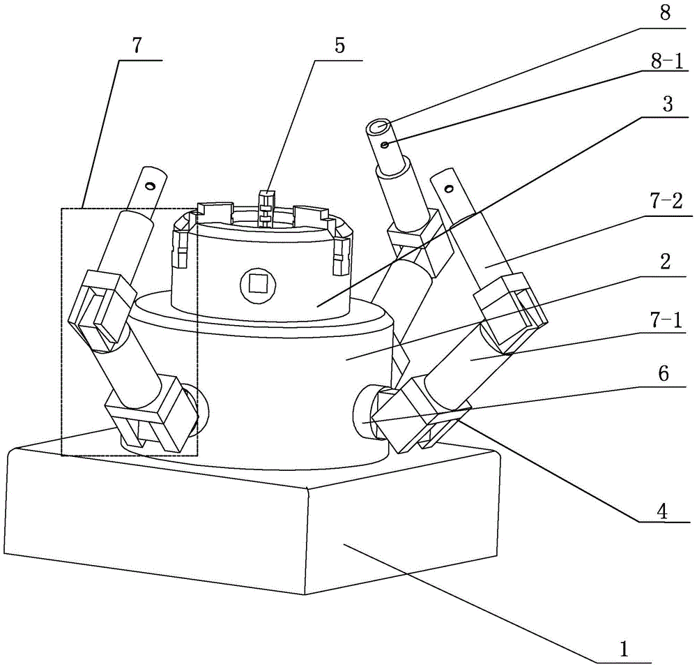
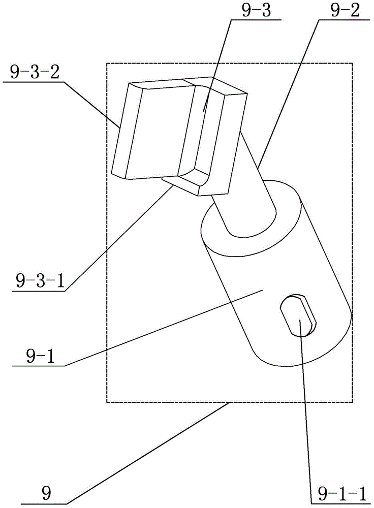
[0030] Specific implementation mode one: combine Figure 1 to Figure 17 This embodiment is described. A fixing device for deep hole drilling and welding blades described in this embodiment includes a base 1, a hydraulic lifting platform 2, a chuck body 3, a first fixing device 9, a second fixing device 10, and a third fixing device 11. Three grippers 4 and multiple claws 5, the hydraulic lifting platform 2 is set in the middle of the upper surface of the base 1, the chuck body 3 is set in the middle of the upper surface of the hydraulic lifting platform 2, and the upper end surface of the chuck body 3 is along the Its circumferential direction is evenly provided with a plurality of claws 5, and the deep hole drill 12 is fixed by a plurality of claws 5, and the upper end surface of the deep hole drill 12 is provided with a center blade 13, an outer blade 14, a first guide block 15, an inner Blade 16 and second guide block 17, each gripper 4 comprises fixed part 6, hydraulic dev...

specific Embodiment approach 2

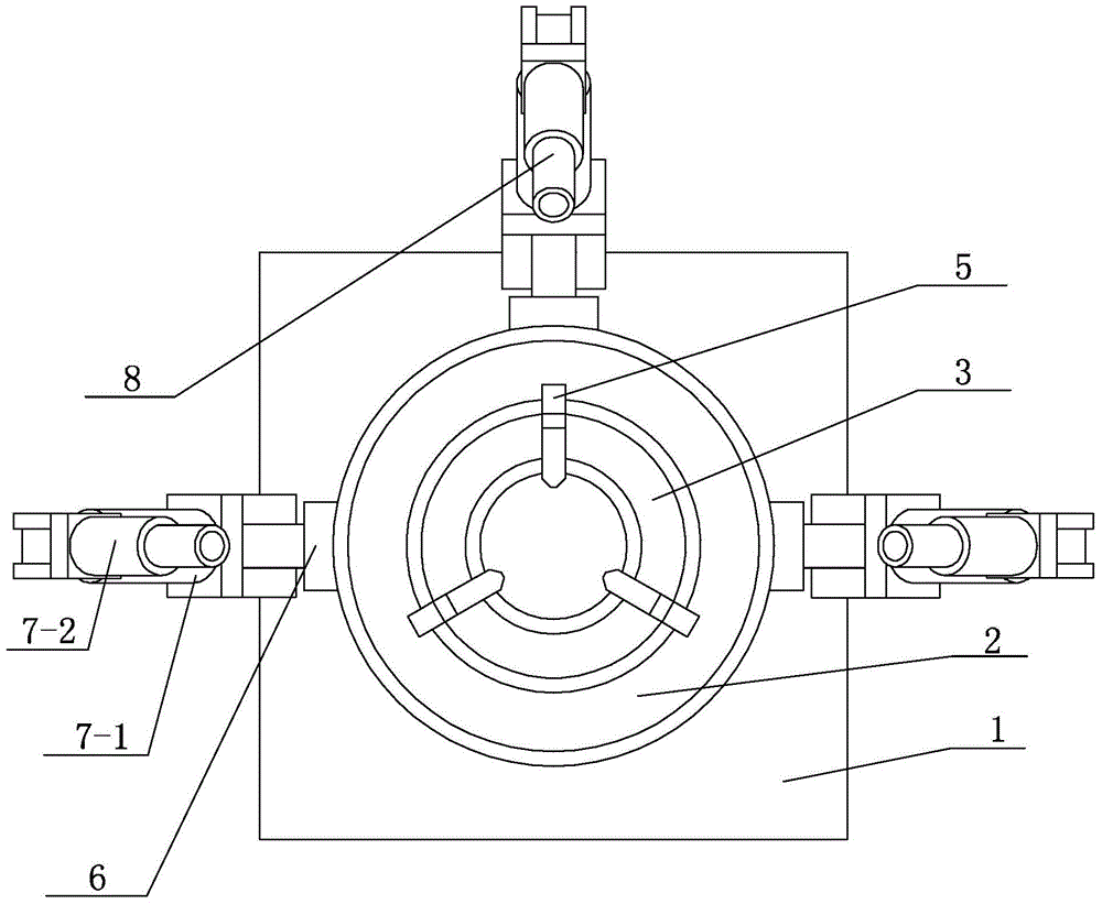
[0035] Specific implementation mode two: combination figure 1 and figure 2 Describe this embodiment, each hydraulic device 7 described in this embodiment includes an intermediate shaft 7-1 and a hydraulic shaft 7-2, one end of the intermediate shaft 7-1 is hinged to the fixed part 6, and the other end of the intermediate shaft 7-1 is connected to the One end of the hydraulic shaft 7-2 is hinged, and the other end of the hydraulic shaft 7-2 is provided with a sleeve 8 . In this way, when each clamping hand is fixed with the blade and the guide block, each boss is in a vertical direction, such as Figure 5 , Figure 9 and Figure 13In this state, the hydraulic shaft 7-2 can be stretched, so that each clamping hand can be clamped with the corresponding center blade 13, outer blade 14, first guide block 15, inner blade 16 and second guide block 17. Tight fix. Other compositions and connections are the same as those in the first embodiment.

specific Embodiment approach 3

[0036] Specific implementation mode three: combination figure 1 Referring to this embodiment, the outer wall of each sleeve 8 in this embodiment is provided with a through hole 8 - 1 along the radial direction of the sleeve 8 , and each sleeve 8 is provided with a spring. Arranged in this way, the spring is used to adjust the depth of the first installation part 9-1, the second installation part 10-1 and the third installation part 11-1 in the respective sleeves 8, so as to ensure that the guide block and the blade are clamped. The clamping force generated when tightening and fixing is uniform, and the phenomenon of uneven clamping force is avoided. Other compositions and connections are the same as those in the second embodiment.


PUM

PropertyMeasurementUnit
lengthaaaaaaaaaa
thicknessaaaaaaaaaa
lengthaaaaaaaaaa

Abstract

The invention relates to a fixing device for a deep hole drill welding blade, and aims to solve the problems of low welding quality and higher rejection rate caused by the condition of possible fall or slip of a welded blade in the process of multiple times of welding needed to finish a blade, a guide block and a drill bit of a traditional deep hole drill. A chuck body is arranged at the middle part of the upper surface of a hydraulic lifting table; multiple clamping jaws are uniformly distributed in the peripheral direction of the upper end surface of the chuck body; a deep hole drill is fixed by the clamping jaws; fixed parts of all grippers are fixedly arranged on the outer side wall of the hydraulic lifting table; and a first fixing device, a second fixing device and a third fixing device are respectively mounted in sleeves of three grippers, and are all made of 3D-printed ceramic materials. The fixing device is applied to the processing field of the deep hole drill welding blade.

Description

technical field [0001] The invention relates to the processing field of deep hole drilling welding blades, in particular to a fixing device for deep hole drilling welding blades. Background technique [0002] Deep hole processing plays a very important role in the machinery manufacturing industry. Deep hole processing is carried out under closed conditions. The cutting conditions are harsh, chip breaking and chip removal are difficult, heat dissipation and cooling are not easy, and the system rigidity is poor, so it is difficult to guarantee processing. Quality, difficulty and importance of deep hole machining technology play an important role in metal cutting. Therefore, good deep hole drilling can improve the level of the current machinery manufacturing industry and bring economic benefits. [0003] The minimum diameter of the deep hole drill is about 16mm. It is a small diameter deep hole drill that can drill deep holes with a ratio of hole depth to hole diameter greater...

Claims


Application Information

Patent Timeline
Patent Type & Authority Patents(China)
IPC IPC(8): B23K37/04B23K3/08B23K1/002
CPCB23K1/002B23K3/087B23K37/0443B23K2101/002
Inventor 吴雪峰苑忠亮杨树财刘献礼
Owner HARBIN UNIV OF SCI & TECH
Why Eureka
Try Eureka