Low-temperature cementing slurry system and composition thereof

A cementing cement slurry and system technology, applied in the direction of drilling composition, chemical instruments and methods, etc., to achieve the effects of promoting low-temperature hydration rate, easy availability of raw materials, and reducing costs

Inactive Publication Date: 2016-04-06
CHINA UNIV OF PETROLEUM (EAST CHINA)
View PDF8 Cites 36 Cited by
  • Summary
  • Abstract
  • Description
  • Claims
  • Application Information

AI Technical Summary

Problems solved by technology

[0008] The purpose of the present invention is to address the challenges faced by deepwater cementing in my country and the problems existing in the existing low-temperature cementing slurry system, by optimizing high-activity silicate materials, silicate nanomaterials, lightening agents, and early strength agents , water loss reducing agent, dispersant and other additives and their dosage form a set of low temperature cementing slurry system suitable for deep water complex environment

Method used


Image

  • Low-temperature cementing slurry system and composition thereof
  • Low-temperature cementing slurry system and composition thereof
  • Low-temperature cementing slurry system and composition thereof

Examples


Embodiment 1

[0035] Example 1: Composition of Low Temperature Cementing Cement Slurry System

[0036] A low-temperature cementing cement slurry system can be composed of the following substances, and the mass parts of each substance are specifically: 100 parts of oil well cement, 125 parts of oil well ultrafine cement, 10.5 parts of nano-silica, and 24.6 parts of active calcium silicate Parts, 26 parts of hollow glass microspheres, 6.2 parts of early strength agent, 4.3 parts of fluid loss reducer, 1.36 parts of dispersant, and 165 parts of water.

Embodiment 2

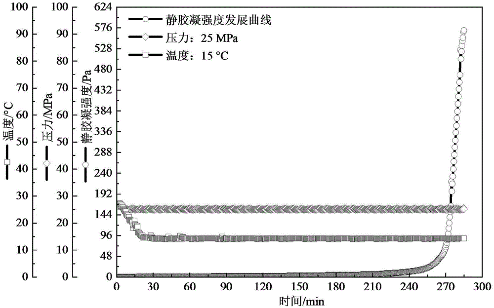
[0037] Example 2: Slurry Performance Test of Low Temperature Cementing Slurry System

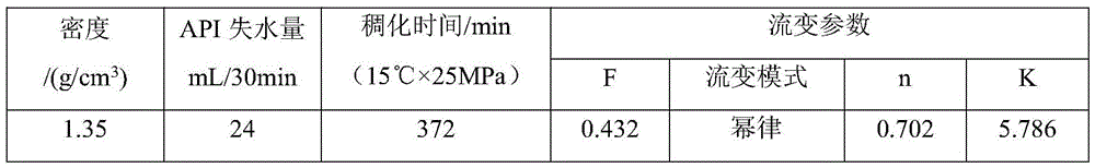
[0038] Taking the low-temperature cementing slurry system of Example 1 as the test object, firstly weigh and mix the solid dry ash component and the liquid water component of the low-temperature cementing slurry system for slurry preparation, and then mix them according to the standard GB / T19139 -2003 "Oil Well Cement Test Method" to prepare slurry, refer to the standard SY / T6544-2003 "Oil Well Cement Slurry Performance Requirements" to measure the mud's density, API water loss, rheological properties and other properties. The test results are shown in Table 1.

[0039] Table 1 Slurry performance of low temperature cementing slurry system

[0040]

Embodiment 3

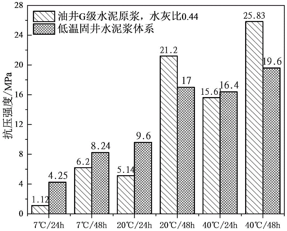
[0041] Example 3: Compressive Strength Test of Low Temperature Cementing Cement Slurry System

[0042] Taking the low-temperature cementing slurry system of Example 1 as the test object, firstly weigh and mix the solid dry ash component and the liquid water component of the low-temperature cementing slurry system for slurry preparation, and then mix them according to the standard GB / T19139 -2003 "Oil well cement test method" to prepare the slurry, measure the compressive strength after curing for 24h and 48h respectively under 10MPa and different temperature conditions, and compare it with the compressive strength of oil well G grade cement slurry (water-cement ratio: 0.44) Compared. The test results are shown in Table 2.

[0043] Table 2 Compressive strength performance of low temperature cementing cement slurry system

[0044]


PUM

PropertyMeasurementUnit
particle sizeaaaaaaaaaa
particle diameteraaaaaaaaaa
particle sizeaaaaaaaaaa

Abstract

The present invention provides a low-temperature cementing slurry system. The slurry system has the characteristics of low density, low temperature early strength and low water loss, and has performances such as thickening time and compressive strength meeting the requirements of deepwater cementing construction site. The low-temperature cementing slurry system comprises the following components by weight: 100 parts of oil well cement, 62-175 parts oil well superfine cement, 7.3-23 parts of nano-silica, 10-32 parts active calcium silicate, 15-50 parts of hollow glass microballoon, 3.6-10 parts of an early strength agent, 3.2-8.6 parts of a fluid loss agent, 0.8-2.0 parts of a dispersing agent and 120-195 parts of water. The low-temperature cementing slurry system has density between 1.30-1.60 g / cm<3>, and is particularly suitable for cementing operations on a deepwater low-temperature surface casing segment. The invention has important significance in reducing the offshore cementing cost, and offshore oil and gas resource exploitation.

Description

technical field [0001] The invention relates to low-temperature cementing technology, in particular to a cement slurry system for deep-water low-temperature well cementing. Relevant requirements for on-site cementing construction. Therefore, the low-temperature cementing cement slurry system is particularly suitable for the cementing operation of the surface casing of the deep-water low-temperature well section. Background technique [0002] my country's offshore oil and gas resources are mainly distributed in the East China Sea, the Bohai Sea and the South China Sea, among which the South China Sea is known as the "second Persian Gulf". The South China Sea is rich in oil and gas resources, but most of its oil and gas resources are buried in deep water areas. As it becomes more and more difficult to stabilize the production of onshore oilfields in my country, it is necessary to develop marine, especially deepwater oil and gas resources as soon as possible. However, the ex...

Claims


Application Information

Patent Timeline
Patent Type & Authority Applications(China)
IPC IPC(8): C09K8/487C09K8/473C04B28/02
CPCC09K8/473C09K8/487C04B28/02C04B2111/00724C04B14/062C04B14/043C04B14/22C04B22/147C04B22/124C04B22/064C04B22/142C04B2103/46C04B2103/408C04B2103/0068
Inventor 王成文陈新徐伟祥孟凡昌
Owner CHINA UNIV OF PETROLEUM (EAST CHINA)
Why Eureka
Try Eureka