
Fluoroplastic-metal valve element and molding technological method thereof

A metal valve core and molding process technology, applied in valve devices, engine components, mechanical equipment, etc., can solve the problems of liquid penetration, poor reliability, high fluorine plastic-metal bonding surface, etc., to improve the bonding performance, good The effect of sealing performance

Inactive Publication Date: 2016-04-06
XIAN AEROSPACE PROPULSION INST
View PDF6 Cites 5 Cited by
  • Summary
  • Abstract
  • Description
  • Claims
  • Application Information

AI Technical Summary

Problems solved by technology

The cold extrusion method is to squeeze the fluoroplastic plastic block into the valve head part without heating. Take the polytetrafluoroethylene cold extrusion valve core as an example. After cold extrusion, the polytetrafluoroethylene is filled behind the valve head part. It can only be cold-bonded with the metal, then rolled and closed to form the valve core. During the manufacturing process, it relies on the cold flow of fluoroplastics for filling. Fluoroplastics cannot be tightly fitted with the metal matrix. There are gaps between the fluoroplastics and the metal matrix, which is easy to Phenomenon such as liquid penetration, poor reliability
The hot pressing method is to put the metal matrix of the valve core that has been sandblasted, cleaned and dried into a hot pressing mold, add fluoroplastics and place it in a hot pressing machine, and then prepare it by melting, cold pressing, shaping, and demoulding. Take FEP-metal spool as an example. During this process, the FEP melt in a viscous flow state has a high viscosity and cannot completely infiltrate the resin melt into the groove of the metal blasting surface, so it cannot Obtain a fluoroplastic-metal bonding surface with high bonding strength
Zhu Jun et al. (CN201510050686) improved the bonding strength of fluoroplastics to metal by coating an adhesive promoter, but the valve core prepared by using this adhesive is reliable in acid and alkali aqueous solution and unsymmetrical dimethylhydrazine and other media. Poor sex

Method used

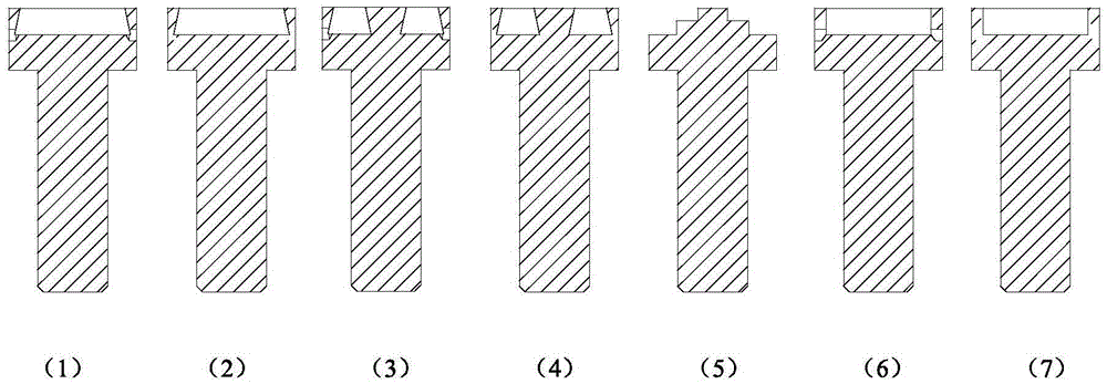
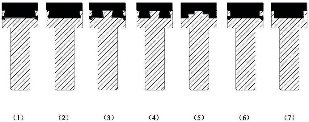
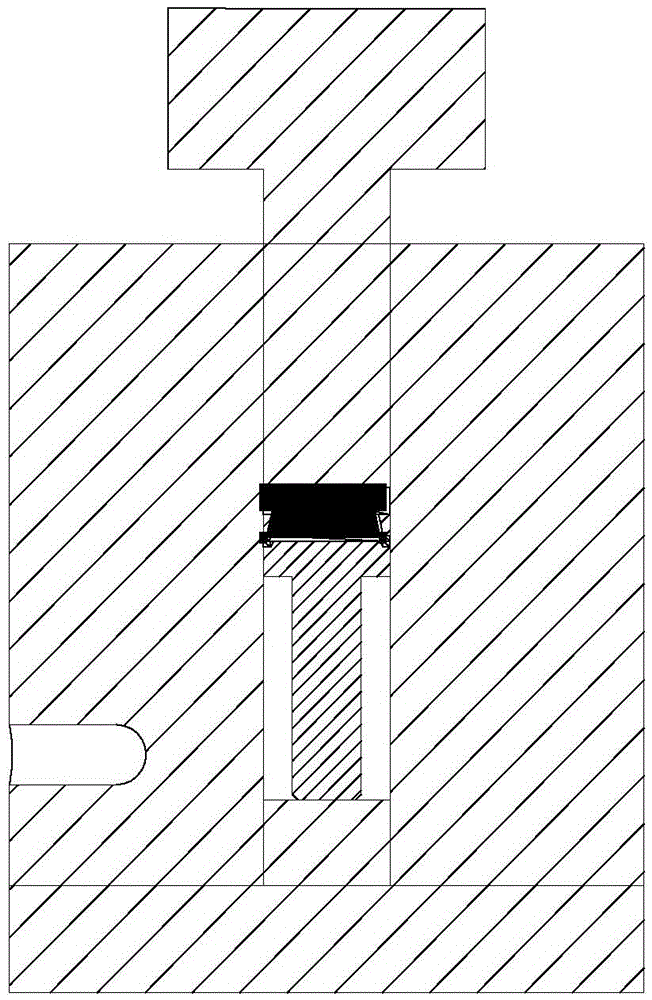

Image

  • Fluoroplastic-metal valve element and molding technological method thereof
  • Fluoroplastic-metal valve element and molding technological method thereof
  • Fluoroplastic-metal valve element and molding technological method thereof

Examples


Embodiment 1

[0024] (1) Cleaning of the metal substrate of the spool: the metal substrate of the spool is cleaned with gasoline and absolute ethanol respectively to remove impurities on the surface of the metal substrate;

[0025] (2) Sandblasting: Use 20-60 mesh quartz sand to sandblast the valve head and the bottom surface, the pressure of the compressed air flow is 0.5MPa, and polish the burrs on the metal edge after sandblasting;

[0026] (3) Clean the sandblasting surface: Soak the metal substrate of the valve core in gasoline for 24 hours after sandblasting, then use a brush dipped in gasoline and alcohol to clean the sandblasting surface twice, dry naturally and store in a desiccator;

[0027] (4) FEP transition layer spraying: place the metal substrate of the valve core with the sandblasted side upward, place it on the substrate fixing tool and transfer it to the sintering furnace. After the sintering furnace is heated to 310 ° C, the sintered valve core Take out the metal substrat...

Embodiment 2

[0033] (1) Cleaning of the metal substrate of the spool: the metal substrate of the spool is cleaned with gasoline and absolute ethanol respectively to remove impurities on the surface of the metal substrate;

[0034] (2) Sandblasting: use 20-60 mesh quartz sand to sandblast the valve head and the bottom surface, the pressure of the compressed air flow is 0.75MPa, and polish the burrs on the metal edge after sandblasting;

[0035] (3) Clean the sandblasting surface: Soak the metal substrate of the valve core in gasoline for 24 hours after sandblasting, then use a brush dipped in gasoline and alcohol to clean the sandblasting surface for 3 times, dry naturally and store in a desiccator;

[0036] (4) Spraying of polytrifluorochloroethylene transition layer: place the metal substrate of the valve core with the sandblasted side upward, place it on the substrate fixing tooling and transfer it to the sintering furnace. After the sintering furnace is heated to 210 ° C, the sintered va...

Embodiment 3

[0042] (1) Cleaning of the metal substrate of the spool: the metal substrate of the spool is cleaned with gasoline and absolute ethanol respectively to remove impurities on the surface of the metal substrate;

[0043] (2) Sandblasting: Use 20-60 mesh quartz sand to sandblast the valve head and the bottom surface, the pressure of the compressed air flow is 0.6MPa, and polish the burrs on the metal edge after sandblasting;

[0044] (3) Clean the sandblasting surface: Soak the metal substrate of the valve core in gasoline for 24 hours after sandblasting, then use a brush dipped in gasoline and alcohol to clean the sandblasting surface for 3 times, dry naturally and store in a desiccator;

[0045] (4) Spraying of polyvinylidene fluoride transition layer: Put the sandblasted surface of the valve core metal substrate upwards, place it on the substrate fixing tooling and transfer it to the sintering furnace. After the sintering furnace is heated to 210 ° C, the sintered valve core met...


PUM


Abstract

The invention discloses a fluoroplastic-metal valve element and a molding technological method thereof. The fluoroplastic-metal valve element comprises a valve element metal base body and fluoroplastic attached to the top of the valve element metal base body. The valve element metal base body comprises a valve head and a valve rod. By the adoption of the molding technological method, the valve head is filled with melted fluoroplastic. After a fluoroplastic transitional layer tightly fastened to the metal base body is manufactured between the fluoroplastic and the metal base body, the hot-press molding technological method is adopted, the adhesion strength between the fluoroplastic and the fluoroplastic transitional layer and between the fluoroplastic transitional layer and the metal base body is guaranteed and reaches over 17 MPa, and the sealing performance is reliable.

Description

technical field [0001] The invention belongs to the technical field of plastic molding technology and machinery manufacturing, and relates to a manufacturing technology of a fluoroplastic-metal valve core. Background technique [0002] In the medium-resistant valves used in rocket engines, most of the valve cores adopt a design structure in which fluoroplastics with strong corrosion resistance are embedded in metal substrates. At present, the methods of fluoroplastics embedded in metal substrates are divided into cold extrusion and hot pressing. The cold extrusion method is to squeeze the fluoroplastic plastic block into the valve head part without heating. Take the polytetrafluoroethylene cold extrusion valve core as an example. After cold extrusion, the polytetrafluoroethylene is filled behind the valve head part. It can only be cold-bonded with the metal, then rolled and closed to form the valve core. During the manufacturing process, it relies on the cold flow of fluorop...

Claims


Application Information

Patent Timeline
Patent Type & Authority Applications(China)
IPC IPC(8): F16K51/00B23P15/00
CPCB23P15/001F16K51/00
Inventor 李东升赵新辉姬飞飚沈稚雄
Owner XIAN AEROSPACE PROPULSION INST
Learn More