Circulating air supply system of mechanical grate type garbage gasification incinerator

A mechanical grate and air supply system technology, applied in the direction of incinerator, combustion method, combustion type, etc., can solve the problems of lower heat conversion efficiency, backward heat treatment mode, easy ash accumulation, etc., to improve heat exchange efficiency and ensure heat Ignition loss rate, the effect of preventing secondary pollution

Active Publication Date: 2017-08-04
CHONGQING SANFENG ENVIRONMENTAL IND GRP +1
View PDF2 Cites 3 Cited by
  • Summary
  • Abstract
  • Description
  • Claims
  • Application Information

AI Technical Summary

Problems solved by technology

[0007] 2. With the increasing amount of garbage generated and piled up like mountains, the amount of garbage treatment must be effectively increased in order to meet market demand
[0010] Existing gasification incinerators, such as the following two invention patents: Multi-column segmented drive compound domestic waste incinerator (ZL200710092508.9) and two-stage waste incinerator (ZL201010268376.2) Unsolved problems: heat treatment of waste The mode is relatively backward, just drying-burning-burning, the process of solid combustion releasing heat; the thermochemical reaction in the furnace is dominated by oxidation reaction, supplemented by reduction reaction, which is easy to produce secondary pollutants; when garbage is burned in the furnace, the peroxygen coefficient Large, large amount of primary air and secondary air supply, high dust content in flue gas, great impact on heat energy recovery system and flue gas treatment system, easy to accumulate dust, large amount of flue gas, reducing heat conversion efficiency; Without a separate gasification furnace and ember furnace, waste can only be processed in batches, and large-scale continuous gasification and incineration of waste cannot be realized, and the amount of waste treated is small

Method used


Image

  • Circulating air supply system of mechanical grate type garbage gasification incinerator
  • Circulating air supply system of mechanical grate type garbage gasification incinerator

Examples


Embodiment Construction

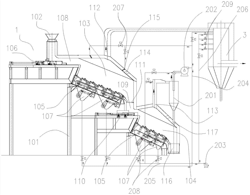
[0031] see figure 1 , is a preferred embodiment of the circulating air supply system of the mechanical grate type garbage gasification incinerator, including a gasification incinerator 1, the gasification incinerator 1 includes a furnace frame 101, and on the furnace frame 101 A feed bin 102, a gasifier 103 and an ember furnace 104 are arranged in sequence along the feeding direction. The rear of the ember furnace 104 is the slag outlet of the ember furnace 104. The gasifier 103 is mainly used for the charcoal part of the garbage. Gasification is carried out, and combustible gasification flue gas and garbage residues are discharged, and the burner 104 is mainly used for burning charcoal residues, and harmless ash is discharged. The hearth 105 of the gasification furnace 103 and the ember furnace 104 adopts a mechanical grate type movable hearth 105 independently driven by sections. The plates are stacked front and back, arranged alternately and gathered together. Multiple gro...


PUM


Abstract

The invention discloses a circulating air supply system of a mechanical fire gate type waste gasification incinerator. The circulating air supply system comprises a gasifier and a combustion furnace. A primary air chamber is arranged below the gasifier and a furnace hearth of the combustion furnace. The gasifier is provided with a secondary air supply port and a first smoke outlet. The combustion furnace is provided with a second smoke outlet. The circulating air supply system further comprises a dust removal device, a first draught fan and a second draught fan. The air inlet end of the dust removal device is connected with the second smoke outlet. The air outlet end of the dust removal device is connected with the air inlet end of the first draught fan. The air outlet end of the first draught fan is connected with a first manifold. A branch pipe of the first manifold is communicated with the primary air chamber of the combustion furnace and the secondary air supply port. The air outlet of the second draught fan is connected with a second manifold. A branch pipe of the second manifold is communicated with the primary air chamber of the combustion furnace and the two ends of the dust removal device. After the circulating air supply system is used, continuous gasifying incineration disposal of a large scale of waste can be achieved, heat losses can be reduced, heat exchange efficiency can be improved, the heat recovery efficiency is high, and the discharge quantity of pollutants can be effectively reduced.

Description

technical field [0001] The invention belongs to the technical field of solid waste incineration treatment, in particular to a circulating air supply system of a mechanical grate type garbage gasification incinerator. Background technique [0002] The existing waste treatment technologies mainly include incineration, sanitary landfill, composting, and waste recycling. Among the conventional waste treatment technologies, incineration has the advantages of obvious reduction effect, complete harmlessness, small land occupation, utilization of waste heat energy, and less secondary pollution, which meets the strategic requirements of my country's sustainable development. However, with the continuous improvement of environmental protection requirements at home and abroad, how to strengthen the control of secondary pollution is particularly important. Therefore, waste pyrolysis and gasification incineration technology is gradually pushed to the road of industrial application, espec...

Claims


Application Information

Patent Timeline
Patent Type & Authority Patents(China)
IPC IPC(8): F23G5/027F23G5/44
CPCF23G5/027F23G5/44F23G2201/40
Inventor 丁又青林顺洪李长江徐明杨鲁柏继松季炫宇田野阳小燕
Owner CHONGQING SANFENG ENVIRONMENTAL IND GRP
Why Eureka
Try Eureka