Flexible underwater storage tank
A storage tank and flexible technology, applied in the field of independent petroleum storage devices, can solve the problems of heavy tank body, thick design, fatigue cracking, etc., and achieve the effect of reducing investment cost and overcoming oil pollution.
- Summary
- Abstract
- Description
- Claims
- Application Information
AI Technical Summary
Problems solved by technology
Method used
Image
Examples
Embodiment 1
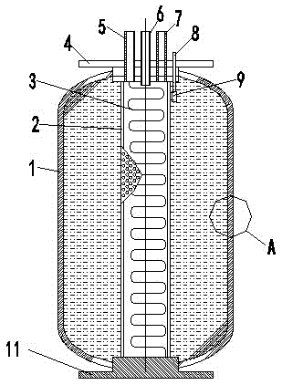
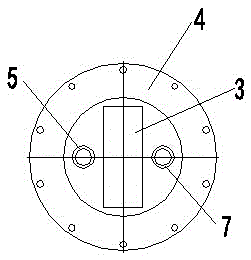
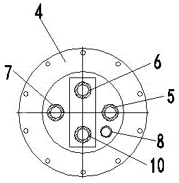
[0044] Embodiment 1, the flexible underwater storage tank of the present invention adopts a shellless type flexible unit tank body and a shell type flexible unit tank body. Such as figure 1 , 2 , 3, wherein the shellless flexible unit tank body includes a unit tank body 1, an upper flange 4 is installed on its upper part, a lower flange 11 is installed on its lower part, and a heater 3 is installed in the inner center of the tank body. In order to prevent the impact on the heater 3 when the tank is evacuated, a protective cylinder 2 with a through hole on the side wall is installed outside the radiator 3, and the oil in the tank can enter through the through hole on the protective cylinder 2 and come into contact with it. The outer surface of the heater 3, thereby realizing contact heating. An oil inlet pipe and an oil outlet pipe for oil supply to enter and exit are installed on the upper flange 4 . The heating device includes a water exchange pipe spirally coiled in the p...
Embodiment 2
[0049] Embodiment 2, the shell-type flexible underwater unit tank body of the present invention still uses the unit body as the basic combination unit, compared with the shell-less flexible underwater storage tank still using the unit, mainly in order to improve safety, in the unit tank A metal shell 40 is added outside the body 1 . Figure 13 is a specific embodiment thereof. The metal shell 40 is a regular hexagonal metal plate structure, which is combined with the unit tank body 1 and the upper and lower flanges to form a closed box structure. The top of the metal shell 40 is installed on the upper fixed flange 71 through the upper connecting bolt 43, and the bottom is installed on the lower fixed flange 77 through the lower connecting bolt 60, never sealing the metal shell. Connecting bolts 42 are installed on the upper peripheral edge and the lower peripheral edge of the metal shell 40, which can realize the connection between the unit bodies, Figure 14 It shows the wa...
PUM
 Abstract
Description
Claims
Application Information
 - R&D
- Intellectual Property
- Life Sciences
- Materials
- Tech Scout
- Unparalleled Data Quality
- Higher Quality Content
- 60% Fewer Hallucinations
Browse by: Latest US Patents, China's latest patents, Technical Efficacy Thesaurus, Application Domain, Technology Topic, Popular Technical Reports.
© 2025 PatSnap. All rights reserved.Legal|Privacy policy|Modern Slavery Act Transparency Statement|Sitemap|About US| Contact US: help@patsnap.com


