Mechanical fire grate type rubbish gasification incinerator and dual-boiler energy-saving power generation system thereof

A mechanical grate, energy-saving power generation technology, applied in the direction of mechanical equipment, machines/engines, incinerators, etc., can solve the problems of easy ash accumulation, large supply, short ash cleaning maintenance cycle, etc., to achieve less waste residue, utilization high rate effect

Active Publication Date: 2016-05-18
CHONGQING SANFENG ENVIRONMENTAL IND GRP +1
View PDF7 Cites 3 Cited by
  • Summary
  • Abstract
  • Description
  • Claims
  • Application Information

AI Technical Summary

Problems solved by technology

At the same time, the fly ash content in the flue gas after incineration is high, the boiler ash is heavy, and the ash cleaning maintenance period is short
[0007] 2. With the increasing amount of garbage generated and piled up like mountains, the amount of garbage treatment must be effectively increased in order to meet market demand
[0010] Existing gasification incinerators, such as the following two invention patents: Multi-column segmented drive compound domestic waste incinerator (ZL200710092508.9) and two-stage waste incinerator (ZL201010268376.2) Unsolved problems: heat treatment of waste The mode is relatively backward, just drying-burning-burning, the process of solid combustion releasing heat;

Method used


Image

  • Mechanical fire grate type rubbish gasification incinerator and dual-boiler energy-saving power generation system thereof
  • Mechanical fire grate type rubbish gasification incinerator and dual-boiler energy-saving power generation system thereof
  • Mechanical fire grate type rubbish gasification incinerator and dual-boiler energy-saving power generation system thereof

Examples


Embodiment Construction

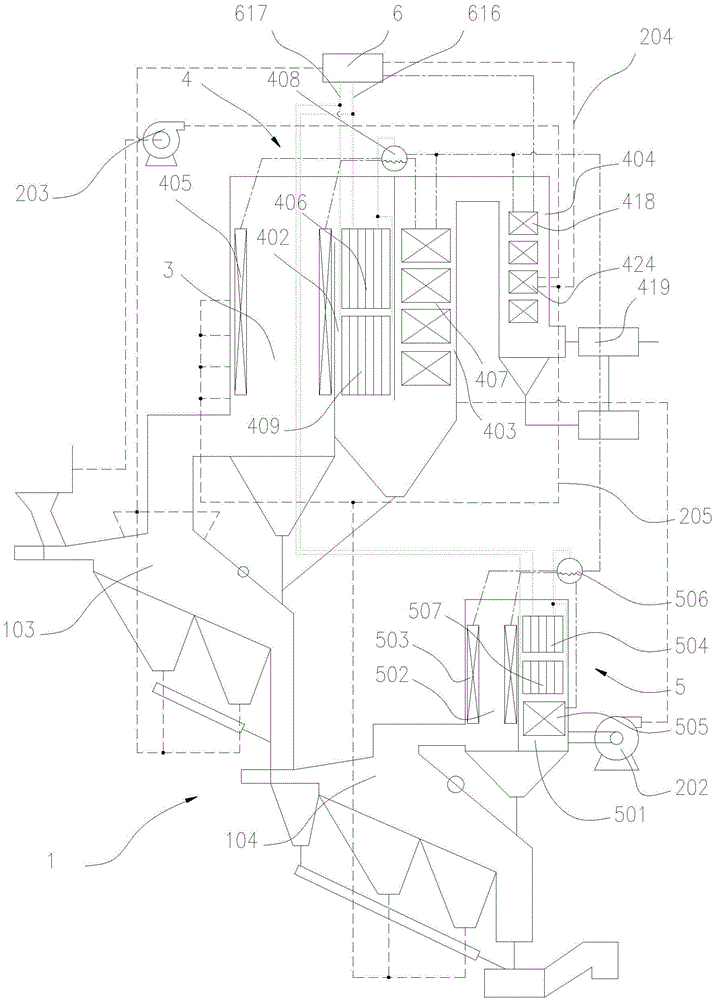
[0050] See Figure 1 to Figure 6 , Is a preferred embodiment of a mechanical grate type garbage gasification incinerator and its dual-boiler energy-saving power generation system, including a gasification incinerator 1, a boiler system, a circulating air supply system, and a power generation system 6.

[0051] See Image 6 , Is a mechanical grate type garbage gasification incinerator, including a grate 101, and a feeding bin 102, a gasification furnace 103, and an incinerator 104 that are sequentially arranged on the furnace rack 101 along the feeding direction. Behind is the slag outlet 116 of the incinerator 104. The slag outlet 117 of the incinerator 104 is provided. The slag outlet 116 of the incinerator 104 is located directly under the slag outlet 117 of the incinerator. The structure has a good sealing effect and can effectively reduce pollutant emissions. The gasification furnace 103 mainly gasifies the carbon-containing part of the garbage and discharges combustible gasi...


PUM


Abstract

The invention discloses a mechanical fire grate type rubbish gasification incinerator which is smaller in heat efficiency conversion loss and higher in heat recovery rate and a dual-boiler energy-saving power generation system of the mechanical fire grate type rubbish gasification incinerator. The mechanical fire grate type rubbish gasification incinerator comprises a gasification incinerator body, a boiler system, a circulation air supply system and a power generation system; the gasification incinerator body comprises a gasification boiler and a burning ash boiler which can be sealed or communicated; the boiler system comprises boiler bodies a and b, the boiler body a is provided with a cyclone burning chamber and boiler chambers a and b, the boiler body b is provided with a boiler chamber d and a cyclone dust removal chamber, water cooling walls are arranged in the cyclone burning chamber and the cyclone dust removal chamber, a superheater unit is arranged in the boiler chamber a, and an evaporator is arranged in the boiler chamber b; and a superheater unit and an evaporator are arranged in the boiler chamber d, steam pockets are arranged at the top ends of the two boiler bodies, a smoke inlet of the cyclone burning chamber is connected with a smoke outlet of the gasification incinerator body, and a smoke inlet of the cyclone dust removal chamber is connected with a smoke outlet of the burning ash boiler. The power generation system comprises a steam input pipe, a steam turbine and a power generator, and the steam input pipe is connected with the superheater units a and b and the steam turbine.

Description

Technical field [0001] The invention belongs to the technical field of solid waste incineration treatment, and in particular relates to a mechanical grate type garbage gasification incinerator and its double boiler energy-saving power generation system. Background technique [0002] The existing waste treatment technologies mainly include incineration, sanitary landfill, composting, and waste recycling. Among the conventional technologies for waste treatment, incineration treatment has the advantages of obvious reduction effect, thorough harmlessness, small land occupation, waste heat energy utilization, and less secondary pollution, which is in line with the strategic requirements of my country's sustainable development. However, with the continuous improvement of environmental protection requirements at home and abroad, how to strengthen the control of secondary pollution is particularly important. Therefore, waste pyrolysis, gasification and incineration technology has been g...

Claims


Application Information

Patent Timeline
IPC IPC(8): F23G5/027F23G5/14F23G5/44F23G5/46F22G1/12F22B33/18F01D15/10
CPCY02E20/12F23G5/027F01D15/10F22B33/18F22G1/12F23G5/14F23G5/44F23G5/46F23G2201/40
Inventor 周雄林顺洪李长江丁又青徐明杨鲁柏继松季炫宇李伟
Owner CHONGQING SANFENG ENVIRONMENTAL IND GRP
Why Eureka
Try Eureka