Rapid multifunctional electronic component temperature characteristic measuring instrument and testing cavity

A technology of electronic components and temperature characteristics, applied in the electronic field, can solve the problems of limited heating temperature range, slow system response speed, large volume, etc., and achieve the effects of reduced equipment volume, high degree of automation, and small equipment volume

Active Publication Date: 2016-05-18
SUN YAT SEN UNIV
View PDF11 Cites 15 Cited by
  • Summary
  • Abstract
  • Description
  • Claims
  • Application Information

AI Technical Summary

Problems solved by technology

[0010] 1. The invention described in REF01 can measure a relatively large amount, but cannot measure the temperature characteristics of the parameters of multi-pin devices such as triodes, MOS tubes and ICs; due to the use of liquid nitrogen refrigeration, the overall volume of the equipment is relatively large , poor portability; limited by the technical level of the era, the temperature characteristics of the measured parameters need to be measured manually at each set temperature point, and the data collection and recording cannot be completed automatically
[0011] 2. The invention described in REF02 only involves double-terminal components, and due to the limitation of the single-chip AD converter, the measurement function and accuracy range are relatively limited. The heating method is controlled by a solenoid valve, which determines that the response speed of heating and cooling will be relatively slow. Slow, the liquid nitrogen cooling and resistance heating methods adopted also determine the large size of the equipment and are not portable
In addition, the invention does not reflect the scalability of the equipment
[0012] 3. The invention described in REF03 is only used for the measurement of resistance temperature characteristics. The heating element is the resistance to be tested itself, which saves the heating mechanism, but at the same time, it also has great limitations. For example, for resistance with high impedance, its constant current source The output voltage will be very high, the output power will be limited, and its heating temperature range will also be limited; its cooling method is natural cooling, resulting in a slow system response
The invention is limited to measuring the temperature characteristics of resistive elements with low impedance
[0013] 4. The invention described in REF04 is designed specifically for measuring MOS devices, it is not inherently scalable, and does not consider cooling mechanisms
[0014] Most of the existing inventions and published documents on measuring the temperature characteristics of components focus on measuring the temperature characteristics of a specific parameter of a specific component, in terms of the scalability of equipment functions and the scalability of measurement accuracy , without much consideration

Method used


Image

  • Rapid multifunctional electronic component temperature characteristic measuring instrument and testing cavity
  • Rapid multifunctional electronic component temperature characteristic measuring instrument and testing cavity
  • Rapid multifunctional electronic component temperature characteristic measuring instrument and testing cavity

Examples


Embodiment 1

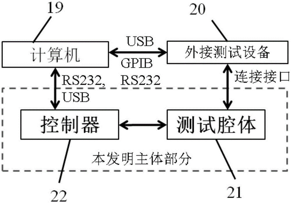
[0058] Embodiment 1: The controller 22 is connected to the test cavity 21 for measurement

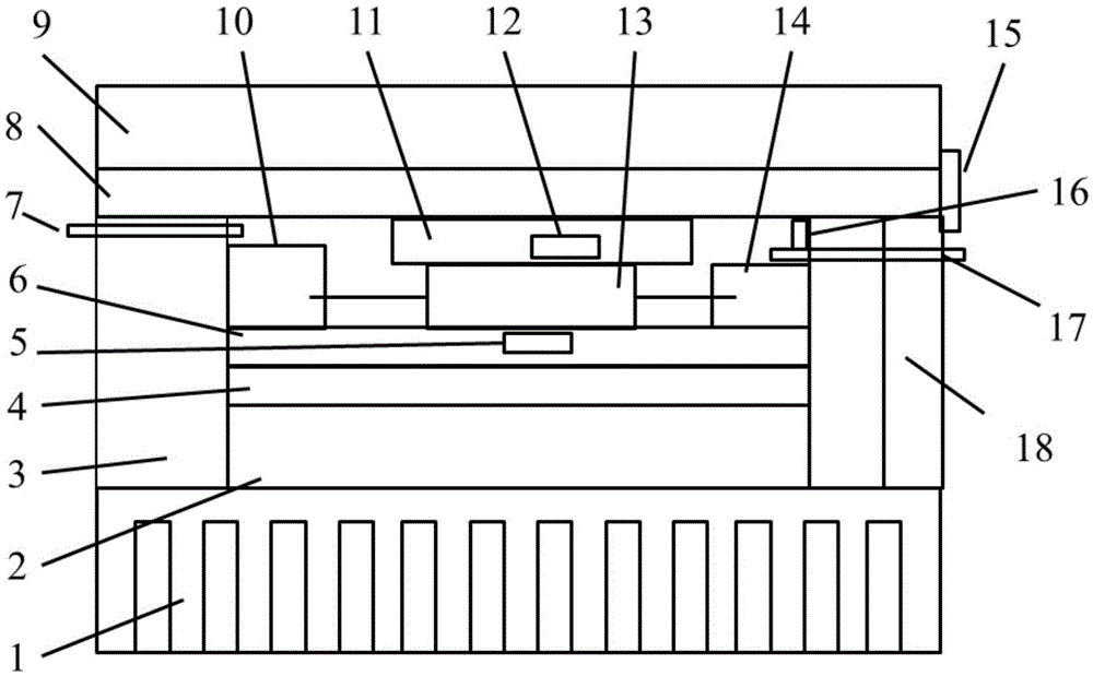
[0059] When the pins of the sample to be tested are less than 4, the user selects the appropriate component bracket 13 to be tested according to the size of the sample to be tested or the component, installs it on the component bracket 13 to be tested, and inserts the component bracket 13 to be tested into the test cavity On the quick connection terminals (10, 14) in 21, cover the detachable cavity top cover 9 and fasten the clamp 15, confirm that the equipment is in normal working condition through the LCD, and remind the user to perform dehumidification operation if the detected humidity is too high . The user enters through the keyboard, selects the parameters to be measured, sets the temperature parameters, sets the test signal parameters, etc., and then starts the measurement. The controller 22 will control the temperature of the test chamber 21 according to the temperature set by...

Embodiment 2

[0060]Embodiment 2: The computer 19 is connected to the controller 22 to connect to the test cavity 21 for measurement

[0061] When the pins of the sample to be tested are less than 4, the user selects a suitable sample holder and the component to be tested bracket 13 according to the size of the sample to be tested or the component, installs it on the component to be tested bracket 13, and inserts the component to be tested bracket 13 into the test On the quick connection terminals (10,14) in the cavity (21), cover the cavity top cover 9 that the top cover can be separated and fasten the presser 15, and confirm the controller 22 and test by the special control program on the computer. The cavity 21 is in a normal working state, and if the detected humidity is too high, the user is reminded to perform a dehumidification operation. Through the computer program interface, the user selects the parameters to be measured, sets the temperature parameters, sets the test signal param...

Embodiment 3

[0062] Embodiment 3: Computer 19, external measuring equipment 20, controller 22 and test chamber 21 perform joint measurement

[0063] When the pins of the sample to be tested are less than 4, the user selects a suitable sample holder to be tested on the component bracket 13 according to the size of the sample to be tested or the component, installs it on the component to be tested bracket 13, and installs the component to be tested bracket 13 to the test On the quick connection terminals (10, 14) in the cavity (21), select the above-mentioned "2+1" external connection mode during installation, and connect to the three BNC interfaces on the external device connection interface on the outer wall of the cavity When the pins of the sample to be tested are greater than 3 and less than 13, the user selects the sample rack to be tested component support 13 that supports 12-pin connection according to the sample to be tested or the component size, and installs it on the component to ...


PUM


Abstract

The invention provides a rapid multifunctional electronic component temperature characteristic measuring device and instrument, and a testing cavity. Temperature characteristic curves of parameters such as capacitance, inductance, resistance, dielectric coefficients, dielectric loss, voltage-current curves and spontaneous polarization of a plurality of electronic components and material samples can be measured. The rapid multifunctional electronic component temperature characteristic measuring device and instrument and the testing cavity is small in size, light in weight, high in speed, high in automatic degree, multi-functional, high in precision and low in cost. The device, instrument and the testing cavity can be applied by an enterprise to rapidly detect temperature characteristics of electronic components, can also be used by scientific research laboratories to research temperature characteristics of specific parameters of the devices and the material samples, and can further be used in the aspect such as experiment demonstration and class teaching.

Description

technical field [0001] The invention relates to the field of electronic technology, and relates to a fast multifunctional electronic component temperature characteristic measuring instrument and a testing cavity. Background technique [0002] As an important environmental parameter, temperature directly affects the performance of electronic components. Most electronic equipment failures are caused by excessive temperature. Therefore, the control of temperature and the temperature drift characteristics of electronic component parameters are referred to as "temperature characteristics" for the system. Reliability is key. For semiconductor components, the temperature rise will reduce the maximum allowable power consumption of the transistor, and the rise of the junction temperature will cause the breakdown and damage of the P-N junction. Changes in temperature can lead to changes in the inductance and quality factor of the inductor; lead to changes in the capacitance and diele...

Claims


Application Information

Patent Timeline
Patent Type & Authority Applications(China)
IPC IPC(8): G01R1/04G01R27/26G01R19/00G01R27/02
CPCG01R1/04G01R19/00G01R27/02G01R27/2605G01R27/2611G01R27/2617G01R27/2694
Inventor 林少鹏王延珺李阳薛聪马德才王彪
Owner SUN YAT SEN UNIV
Why Eureka
Try Eureka