
Two-stage down-suction biomass gasifier

A gasifier and biomass technology, which is applied in the gasification process, details of gasification devices, chemical industry, etc., can solve the problems of incomplete activation of coke reactivity, low conversion rate of carbon elements, unfavorable removal of tar, etc. The effect of fast reaction, sufficient tar conversion and low tar content

Inactive Publication Date: 2016-05-25
UNIV OF SHANGHAI FOR SCI & TECH
View PDF8 Cites 17 Cited by
  • Summary
  • Abstract
  • Description
  • Claims
  • Application Information

AI Technical Summary

Problems solved by technology

[0004] Since biomass itself is a poor conductor of heat, if the method of indirect heating and pyrolysis using a pyrolysis cylinder will cause a large heat transfer resistance, which is quite unfavorable to the pyrolysis process, the insufficient pyrolysis will make the tar removal process still difficult. There is tar precipitation, and the reactivity of coke is not fully activated, which is unfavorable for further removal of tar, and it is also the main reason for the low conversion rate of carbon elements
[0005] In a staged downdraft gasifier, the reactivity of coke to tar is the key factor determining the tar content in the gas produced by the downdraft gasifier. During the gasification process, a large number of pore blockages and deactivation processes occur. In order to further reduce the tar content and improve the gasification efficiency during the gasification process, other more effective methods need to be adopted.

Method used


Image

  • Two-stage down-suction biomass gasifier

Examples


Embodiment Construction

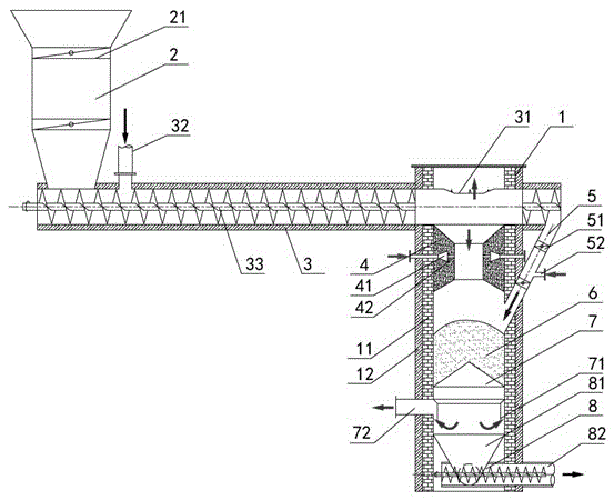
[0020] The following is attached figure 1 The present invention will be further described with examples.

[0021] like figure 1 As shown, the double-stage downdraft biomass gasifier of the present invention mainly consists of a gasification furnace body 1, a furnace wall 11, an insulation layer 12, a feed hopper 2, a gate valve 21, a pyrolysis cylinder 3, and a pyrolysis gas Outlet 31, ash return inlet 32, feed auger 33, concrete throat 4, gas buffer chamber 41, nozzle 42, ash fall pipe 5, ash fall pipe cut-off gate valve 51, ash fall pipe air inlet 52, accumulated ash carbon layer 6. Ash removal grate 7, ash retaining ring 71, gasification gas outlet 72, ash removal device 8, ash collection hopper 81, ash discharge auger 82 and other structures and units.

[0022] The upper part of the gasification furnace body 1 is connected with a pyrolysis cylinder 3, and the pyrolysis cylinder 3 is equipped with a feed auger 33, and the pyrolysis cylinder 3 located in the gasification f...


PUM


Abstract

The present invention relates to a two-stage down-suction biomass gasifier, the upper part of a gasifier body is connected with a pyrolysis tube, a feed auger is arranged in the pyrolysis tube, the pyrolysis tube is provided with a pyrolysis gas outlet, one end of the pyrolysis tube is connected with a feed hopper, a side upper surface of a feed port of the pyrolysis tube is provided with a returning ash inlet, the feed hopper is internally provided with a two-stage cut-off brake valve, the other end of the pyrolysis tube is communicated with an accumulation ash carbon layer in the gasifier body by an ash falling pipe, the ash falling pipe is internally provided with a two-stage ash falling pipe cut-off brake valve and an ash falling pipe air inlet, an ash removal furnace grate, an ash retainer ring and an ash removal device are arranged under the accumulation ash carbon layer of the gasifier body, the ash removal device is connected with an ash discharge auger by an ash collection hopper, and the ash discharge auger is connected with the returning ash inlet. Tar efficient removal and biomass energy efficient conversion can be realized by pyrolysis and solid product separation and difference processing methods, and by homogeneous partial oxidation of pyrolysis components and smoldering combustion oxidation activation of solid coke, reactivity of the pyrolysis components and the solid coke are enhanced, and efficient tar removal and gasification conversion effects can be ultimately realized.

Description

technical field [0001] The invention relates to a biomass gasification furnace, in particular to a biomass gasification furnace of the direct pyrolysis stage of biomass and returned ash and the high-temperature gasification stage of active coke. Background technique [0002] Gasification is an important conversion method of biomass energy, which has the characteristics of cleanness, high efficiency, strong fuel adaptability and flexible operation, and has broad application prospects. Among various biomass gasification technologies, the downdraft gasifier has the lowest tar content in the gas produced, about 0.5g / Nm 3 ; while the suction type is the most, up to 50g / Nm 3 . Although the existing downdraft gasification technology has the lowest tar content in the produced gas, there are still problems such as poor stability of the produced gas quality, small gasification scale, and low energy utilization rate. [0003] Although the tar content of the traditional downdraft bio...

Claims


Application Information

Patent Timeline
IPC IPC(8): C10J3/20C10J3/30C10J3/34C10J3/84
CPCC10J3/20C10J3/30C10J3/34C10J3/84C10J2200/152C10J2200/158C10J2300/0916C10J2300/1631Y02P20/10
Inventor 吴文广吴文潇吴昊展新崔国民
Owner UNIV OF SHANGHAI FOR SCI & TECH
Learn More