
A kind of heat treatment method of n-type silicon chip

A heat treatment method and heat treatment furnace technology are applied in the field of silicon materials, which can solve the problems affecting the conversion efficiency of solar cells and the high impurity content of n-type silicon wafers, and achieve the effects of improving lifespan and improving conversion efficiency.

Active Publication Date: 2018-05-15
ZHONGWEI NEW ENERGY CHENGDU CO LTD
View PDF5 Cites 4 Cited by
  • Summary
  • Abstract
  • Description
  • Claims
  • Application Information

AI Technical Summary

Problems solved by technology

[0008] In view of the shortcomings of the prior art described above, the purpose of the present invention is to provide a heat treatment method for n-type silicon wafers, which is used to solve the problem in the prior art that the impurity content in n-type silicon wafers is too high and affects the conversion efficiency of solar cells

Method used


Image

  • A kind of heat treatment method of n-type silicon chip
  • A kind of heat treatment method of n-type silicon chip
  • A kind of heat treatment method of n-type silicon chip

Examples


Embodiment 1

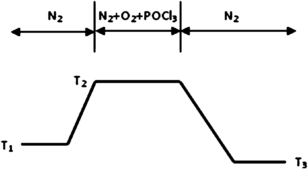
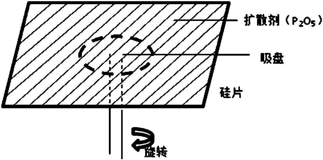
[0042] This embodiment provides a specific implementation method for improving the conversion efficiency of an n-type crystalline silicon heterojunction solar cell by using the heat treatment technology of the present invention. The crystalline silicon heterojunction solar cell is also the SHJ solar cell introduced above.

[0043] In this embodiment, an n-type monocrystalline silicon wafer is used. The four side lengths of the silicon wafer are 156.75 mm, and the rounded corner diameter is 205 mm. After slicing, it is cleaned and packaged in clean plastic for solar cells.

[0044] First, a KOH aqueous solution is used to de-damage the silicon wafer. The concentration of the KOH aqueous solution is 20%, the temperature is 85 degrees, and the etching thickness of one side of the silicon wafer in the thickness direction is about 10 microns. After sufficient water washing, the surface is cleaned with an aqueous solution of ammonia water and hydrogen peroxide, and after water wash...

Embodiment 2

[0059] This embodiment provides another technical path for the n-type doped layer. In this embodiment, the manufacturing method and process of using silicon wafers, heat treatment furnaces and solar cells are exactly the same as those in Embodiment 1.

[0060]Use n-type monocrystalline silicon wafers. The four side lengths of the silicon wafers are 156.75mm, and the diameter of the rounded corners is 205mm. After slicing, they are cleaned and packaged in clean plastic for solar cells.

[0061] First, a KOH aqueous solution is used to de-damage the silicon wafer. The concentration of the KOH aqueous solution is 20%, the temperature is 85 degrees, and the etching thickness of one side of the silicon wafer in the thickness direction is about 10 microns. After sufficient water washing, the surface is cleaned with an aqueous solution of ammonia water and hydrogen peroxide, and after water washing again, the silicon oxide layer on the surface is removed with 2% HF aqueous solution....


PUM

PropertyMeasurementUnit
thicknessaaaaaaaaaa
thicknessaaaaaaaaaa
thicknessaaaaaaaaaa

Abstract

The invention provides a heat treatment method for an n-type silicon wafer. The heat treatment method at least includes the steps that the n-type silicon wafer to be treated is provided, the n-type silicon wafer is put into a heat treatment furnace with a certain temperature, and the temperature is increased to a certain value; oxygen is introduced into the heat treatment furnace; a dispersing agent containing n-type doping elements is supplied to the surface of the n-type silicon wafer so that a silicon oxide layer and an n-type doping layer can be formed on the surface of the n-type silicon wafer; the silicon oxide layer and the n-type doping layer are removed after heat treatment is completed. After the n-type silicon wafer is subjected to heat treatment, recombination centers, caused by the concentration of the doping elements and heat stress, in the n-type silicon wafer can be reduced, the quality and uniformity of the n-type silicon wafer can be improved, the service life of current carriers in the n-type silicon wafer can be prolonged, and thus the conversion efficiency of a solar cell can be improved.

Description

technical field [0001] The invention relates to the field of silicon materials in semiconductor materials, in particular to an n-type silicon wafer heat treatment method. Background technique [0002] Silicon material is the foundation of semiconductor technology. The production of crystalline silicon wafers is the basic material of all silicon-based semiconductor devices, and its quality directly affects the performance of semiconductor devices. In addition to resistivity, the main technical indicators of crystalline silicon wafers include defect and dislocation density, impurity concentration, etc., and its electrical properties are affected by the thermal stress in the manufacturing process and the carrier recombination center caused by impurity elements. As the size of silicon wafers continues to expand, it becomes more and more difficult to control the thermal field distribution and the resulting thermal stress during the production of silicon wafers, which may generate...

Claims


Application Information

Patent Timeline
Patent Type & Authority Patents(China)
IPC IPC(8): C30B33/02C30B29/06H01L31/18
CPCC30B29/06C30B33/005C30B33/02H01L31/1804H01L31/1864Y02E10/547Y02P70/50
Inventor 刘正新祝方舟王栋良刘金宁
Owner ZHONGWEI NEW ENERGY CHENGDU CO LTD
Learn More