Die plasma 3D rapid molding equipment and molding method

A molding equipment and plasma technology, applied in the field of ion 3D rapid prototyping equipment and molding, can solve the problems of high mold production cost, low production efficiency, and high mold production cost

Inactive Publication Date: 2016-06-22
SINOADDITIVE MFG EQUIP CO LTD
View PDF11 Cites 5 Cited by
  • Summary
  • Abstract
  • Description
  • Claims
  • Application Information

AI Technical Summary

Problems solved by technology

The Chinese invention patent application document published on August 27, 2014 with the publication number CN104004966A discloses a casting preparation method for stamping dies. Heat treatment and multi-pass processing are required, the designability of the mold and its performance is poor, and the manufacturing process is cumbersome
The Chinese invention patent application document with the publication number CN104057271A published on September 24, 2014 discloses a powder metallurgy preparation method for cemented carbide tools and molds. Since each mold product corresponds to a pair of molds, the shrinkage of different alloy powders The coefficients are different, and each corresponding mold needs to be designed, resulting in high mold production costs; mold preparation time is long, and the preparation efficiency is low; when powder is filled, under the action of friction, the corners are filled unevenly, resulting in uneven strength , affecting the service life of mold products
In the invention patent "Moulds and methods for making molds and casting methods" published on August 13, 2008 with the publication number CN101242923A, a modular group and method of molds are disclosed. The modular group and Meth

Method used


Image

  • Die plasma 3D rapid molding equipment and molding method
  • Die plasma 3D rapid molding equipment and molding method
  • Die plasma 3D rapid molding equipment and molding method

Examples


Embodiment 1

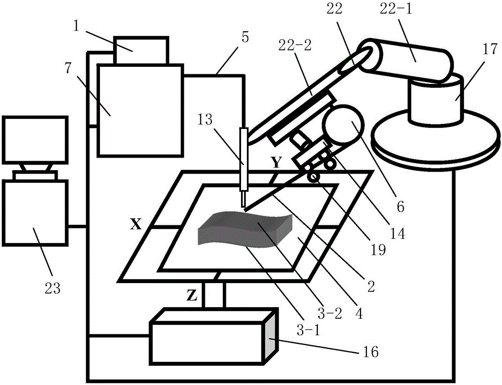
[0088] Such as figure 1A kind of mold plasma 3D rapid prototyping equipment shown is characterized in that: by monitoring system, plasma beam processing system, the horizontal printing table 4 that is placed for the mold to be formed and the mold matrix 3-1 of described mold to be formed Temporarily fixed temporary fixtures; the mold to be formed includes a mold base 3-1 and a molding surface working layer 3-2 arranged on the mold base 3-1; the temporary fixtures are arranged on the horizontal printing table 4.

[0089] The plasma beam processing system consists of a plasma generator equipped with a shower head and used to generate a plasma beam, a gas supply device 1 for supplying working gas to the plasma generator, and a feeding device for continuously sending out the processed wire 2. The wire device and the printing position adjustment device for adjusting the printing position are composed. Both the plasma generator and the wire feeding device are located above the horiz...

Embodiment 2

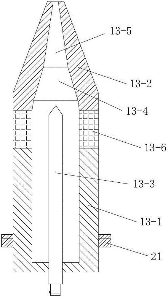
[0201] In this example, if Figure 7 As shown, the difference between the mold plasma 3D rapid prototyping equipment used and the embodiment 1 is that the angle between the nozzle 13-5 and the central axis of the gun body 13-1 is 30°-45°.

[0202] In this way, after changing the direction of the plasma beam through the nozzle 13-5, the thermal load impact of the plasma jet on the anode nozzle 13-2 can be effectively reduced, and the anode ablation condition is improved.

[0203] In this embodiment, the structure, connection relationship and working principle of the rest of the mold plasma 3D rapid prototyping equipment are the same as those in Embodiment 1.

[0204] In this embodiment, the mold plasma 3D rapid prototyping method adopted is the same as that in Embodiment 1.


PUM

PropertyMeasurementUnit
Diameteraaaaaaaaaa
Heightaaaaaaaaaa
Layer thicknessaaaaaaaaaa

Abstract

The invention discloses die plasma 3D rapid molding equipment and molding method. The equipment is composed of a monitoring system, a plasma beam machining system, a horizontal printing table for containing a to-be-molded die and a temporary fixing piece; the plasma beam machining system is composed of a plasma generator, an air supply device, a wire feeding device and a printing position adjusting device; the printing position adjusting device comprises a horizontal movement device and a printing distance adjusting device; and the monitoring system comprises a horizontal movement controller, a temperature detecting unit, a distance detecting unit and a printing distance adjusting controller, and a temperature regulation and control unit is composed of the temperature detecting unit and the printing distance adjusting controller. The molding method includes the steps of (1) three-dimensional model obtaining and layered slicing treatment; (2) scanning path filling; (3) scanning path obtaining; and (4) layer-by-layer printing from bottom to top. The die plasma 3D rapid molding equipment is reasonable in design, easy and convenient to operate, high in efficiency and good in using effect, the molding process is directly executed under the atmospheric environment, and the quality of the die is good.

Description

technical field [0001] The invention belongs to the technical field of rapid prototyping, and in particular relates to a mold plasma 3D rapid prototyping equipment and a prototyping method. Background technique [0002] Mold refers to various molds and tools used in industrial production for injection molding, blow molding, extrusion, die-casting or forging forming, smelting, stamping and other methods to obtain the required products. In short, a mold is a tool used to shape a product. Mold is an important tool in product molding and processing, and the cost accounts for 10% to 30% of product cost. The molding surface of the mold refers to the surface used to shape the product (also called the product), and the molding surface is the surface that directly contacts the molded product. Wherein, the molding surface of the cavity refers to the outer surface for molding the product, and the molding surface of the core is the inner surface for molding the product. The processin...

Claims


Application Information

Patent Timeline
IPC IPC(8): B22F3/105B22F5/00B33Y30/00B33Y10/00
CPCB22F5/007B33Y10/00B33Y30/00B22F10/00B22F10/322B22F12/90B22F12/70B22F12/53B22F10/28Y02P10/25
Inventor 华云峰程国君郝勇魏志宇
Owner SINOADDITIVE MFG EQUIP CO LTD
Why Eureka
Try Eureka