

Sintering flue gas purification system and method achieving energy conservation and emission reduction
A technology for sintering flue gas, energy saving and emission reduction, applied in chemical instruments and methods, separation methods, nitrous oxide capture, etc., can solve the problems of activated coke damage, energy waste, and large investment in activated coke flue gas purification process, etc. Achieve the effect of reducing consumption, reducing investment and operating costs, and realizing energy recycling
- Summary
- Abstract
- Description
- Claims
- Application Information
AI Technical Summary
Problems solved by technology
Method used
Image

Examples
Embodiment 1
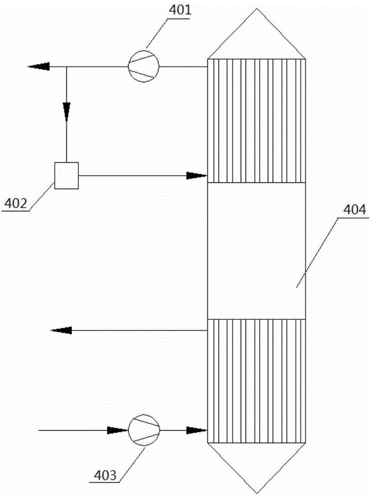
[0059] A sintering flue gas purification system for energy saving and emission reduction, such as figure 2 As shown, it includes sintering machine 1, sintering machine bottom bellows 2, sintering machine large flue 3, heat exchanger 4, electrostatic precipitator 5, sintering main exhaust fan 6, 1# fan 7, adsorption tower 8, chimney 9, 1 #Belt conveyor 10, 1# bucket elevator 11, 2# bucket elevator 12, regeneration tower 13, vibrating screen 14, sintering machine batching system 15, 2# belt conveyor 16, 3# fan 17, gas combustion Device 18, contact acid system 19, 4# fan 20, 2# fan 21, flue gas distributor 22;
[0060] Among them, the sintering machine 1 is connected to the bellows 2 at the bottom of the sintering machine, the bellows 2 at the bottom of the sintering machine is connected to the large flue 3 of the sintering machine, the large flue 3 of the sintering machine is connected to the sintering main exhaust fan 6, and the sintering main exhaust fan 6 is connected to the...
Embodiment 2
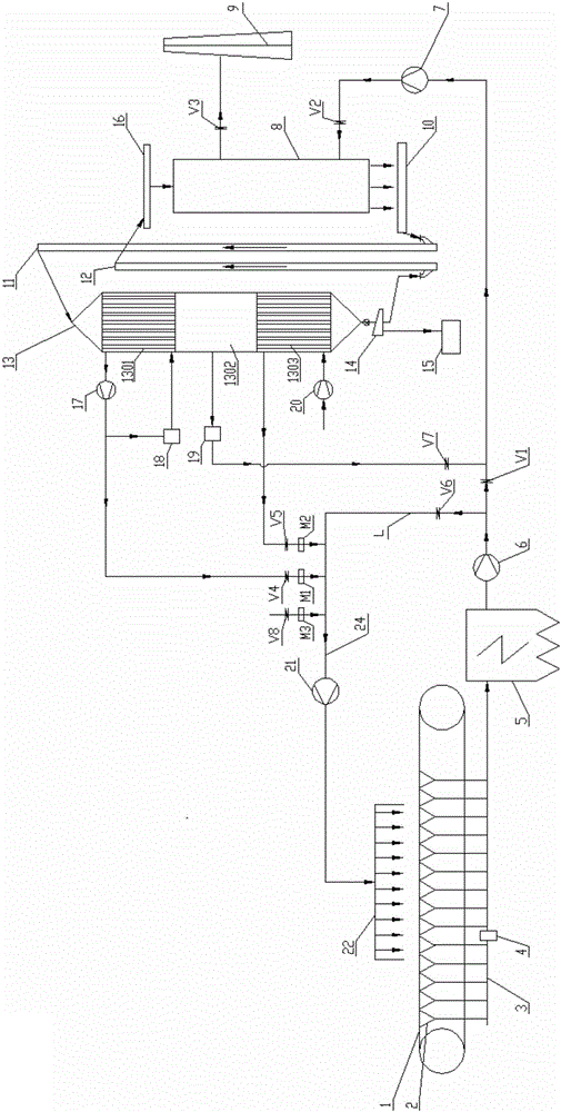
[0074] A sintering flue gas purification system for energy saving and emission reduction, such as image 3 As shown, including sintering machine 1, sintering machine bottom bellows 2, sintering machine large flue 3, electrostatic precipitator 5, sintering main exhaust fan 6, 1# fan 7, adsorption tower 8, chimney 9, 1# belt conveyor 10. 1# Bucket Elevator 11, 2# Bucket Elevator 12, Regeneration Tower 13, Vibrating Screen 14, Sintering Machine Batching System 15, 2# Belt Conveyor 16, 3# Fan 17, Gas Burner 18, Contact Process Acid system 19, 4# fan 20, 2# fan 21, flue gas distributor 22, dust collector 23;
[0075] Among them, the sintering machine 1 is connected to the bellows 2 at the bottom of the sintering machine, several bellows at the head and several bellows at the tail of the bellows 2 at the bottom of the sintering machine are connected to the dust collector 23, and the remaining bellows are connected to the large flue 3 of the sintering machine, and the large bellows o...
Embodiment 3
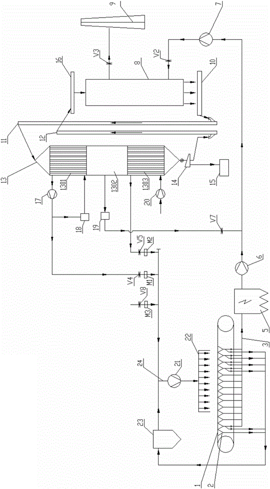
[0087] The method for purifying sintering flue gas using the energy-saving and emission-reducing sintering flue gas purification system of Embodiment 1 comprises the following steps:
[0088] 1) Heat utilization of sintering machine flue gas
[0089] The high-temperature flue gas generated by the sintering of the sintering machine enters the large sintering flue through the bellows at the bottom of the sintering machine. The flue gas passes through the heat exchanger for heat exchange, and passes through the electric dust collector and the sintering main exhaust fan. Part of the flue gas is pressurized by the 1# fan and enters the adsorption The other part of the flue gas enters the pipe at the front end of the 2# fan from the circulating flue gas pipe as the circulating flue gas; by adjusting the flow of water in the heat exchanger, the heat exchange is adjusted to ensure that the temperature of the flue gas entering the tower is controlled at 120~ 140°C; after heat exchange ...
PUM
| Property | Measurement | Unit |
|---|---|---|
| Particle size | aaaaa | aaaaa |
| Particle size | aaaaa | aaaaa |
Abstract
Description
Claims
Application Information