Vacuum laser welding system for grillwork
A laser welding and laser welding head technology, applied in laser welding equipment, welding equipment, metal processing equipment, etc., can solve the problems of long vacuuming time, long waiting time for workpiece welding, and inability to meet the needs of high-efficiency production. The effect of vacuum pumping efficiency, good beam pointing stability and strong beam quality stability
- Summary
- Abstract
- Description
- Claims
- Application Information
AI Technical Summary
Problems solved by technology
Method used
Image

Examples
specific Embodiment approach 1
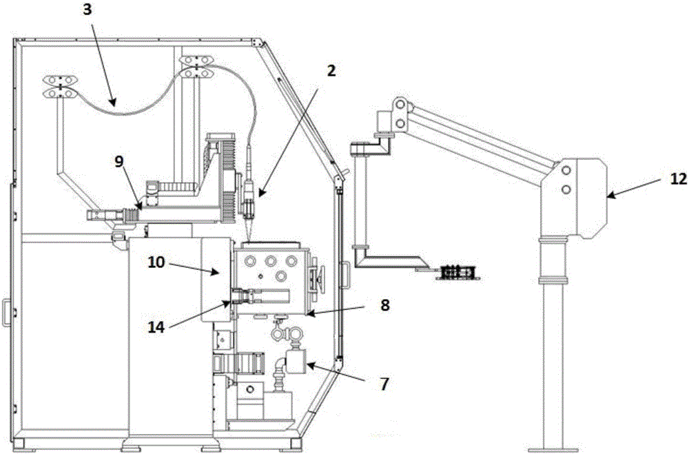
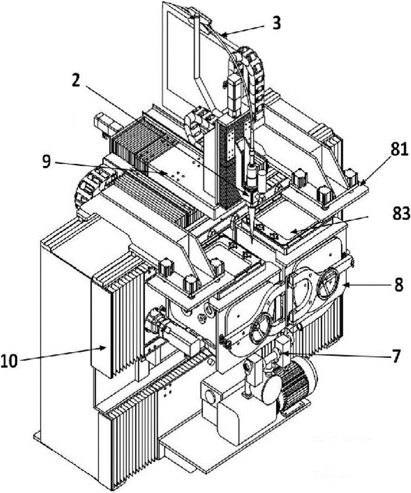
[0019] Specific implementation mode one: see Figure 1 to Figure 5 Describe this embodiment, the lattice vacuum laser welding system described in this embodiment, it includes laser 1, laser welding head 2, optical cable 3, cable, water cooling system 5, CCD monitoring system 6, vacuum argon filling system 7, vacuum chamber 8. Three-dimensional motion mechanism 9, workpiece displacement mechanism 10, computer 11, handling manipulator 12, master control system 13 and servo system 14;
[0020] The laser welding head 2 is fixed on the three-dimensional motion mechanism 9, the three-dimensional motion mechanism 9 drives the laser welding head 2 to move, the laser signal input port of the laser welding head 2 is connected to the laser signal output port of the laser 1 through the optical cable 3, and the vacuum chamber 8 is arranged on Right below the laser welding head 2, the vacuum chamber 8 is an airtight rectangular box, the upper side wall of the box is light-transmitting glass...
specific Embodiment approach 2
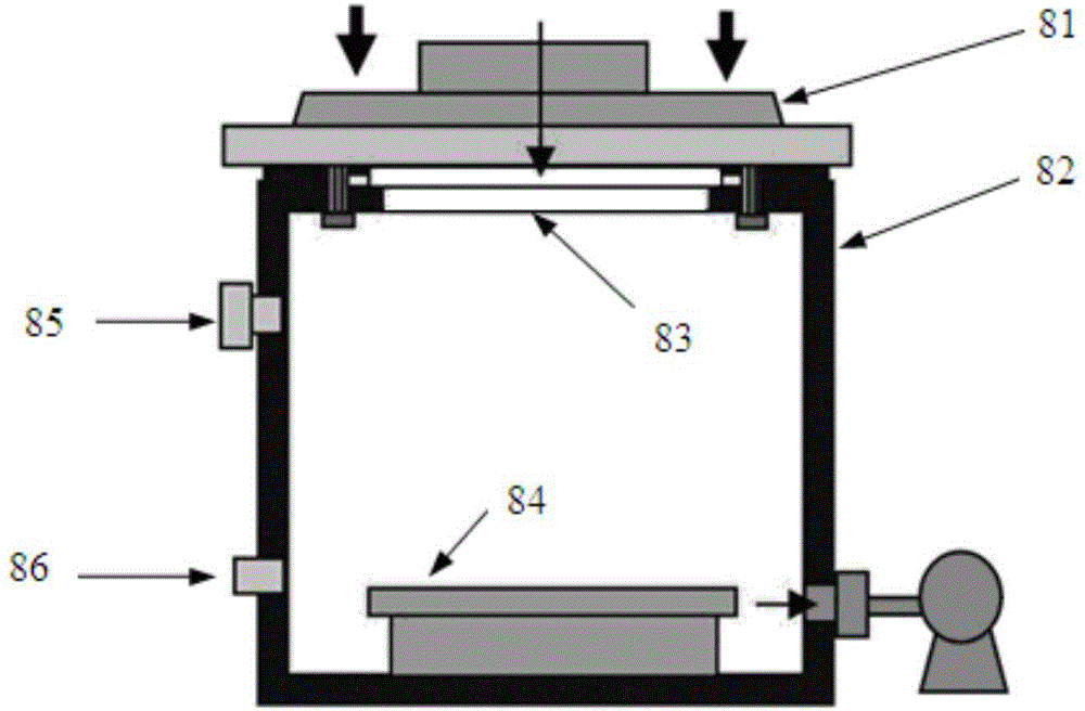
[0028] Embodiment 2: Further description of the grid vacuum laser welding system described in Embodiment 1. The vacuum argon filling system includes a vacuum pump, two solenoid valves, a gas pressure sensor and an argon flushing device;
[0029] The vacuum port of the vacuum pump communicates with the vacuum port on the right side wall of the vacuum chamber 8. An electromagnetic valve is arranged between the vacuum port of the vacuum pump 15 and the vacuum port of the vacuum chamber 8. The argon filling port 85 on the left side wall of the chamber 8 is connected, and a solenoid valve is provided between the argon flushing tube port of the argon device and the argon filling port 85 on the left side wall of the vacuum chamber 8, and the gas pressure sensor is used to collect the vacuum chamber 8, the signal output end of the pressure sensor is the state signal output end of the vacuum argon flushing system 7, and the control signal input ends of the two solenoid valves are the co...
specific Embodiment approach 3
[0030]Embodiment 3: Further description of the grid vacuum laser welding system described in Embodiment 2, which also includes an exhaust switch, and the exhaust switch is arranged outside the exhaust port 86 of the vacuum chamber 8 . The equipment in this embodiment includes the switch of the argon filling valve and exhaust valve of the circuit; the switch and measurement of the vacuum gauge; the switch and display of each MFC; the left and right movement and flip control of the grid; the power failure alarm control of each power supply ; In case of sudden failure of the system, all power should be cut off immediately. The numerical control system detects the state of the gas in the vacuum box through the sensor in the vacuum argon filling box, controls the process of vacuuming and argon filling, and completes the control of the welding preparation process of the vacuum chamber protective gas atmosphere. And through the precise control of the rodless cylinder, the switch betw...
PUM
 Abstract
Description
Claims
Application Information
 - R&D
- Intellectual Property
- Life Sciences
- Materials
- Tech Scout
- Unparalleled Data Quality
- Higher Quality Content
- 60% Fewer Hallucinations
Browse by: Latest US Patents, China's latest patents, Technical Efficacy Thesaurus, Application Domain, Technology Topic, Popular Technical Reports.
© 2025 PatSnap. All rights reserved.Legal|Privacy policy|Modern Slavery Act Transparency Statement|Sitemap|About US| Contact US: help@patsnap.com