Reinforced configuration memory array and configuration method suitable for FPGA used in aerospace

A memory array and memory cell array technology, which is applied in the field of integrated circuits, can solve the problems that the configuration memory array cannot work normally, the FPGA consumes a lot of current, and affects the realization of system functions, so as to solve the problem of power-on surge current and improve the Maximum operating speed and frequency, the effect of improving reliability

Active Publication Date: 2019-07-23
BEIJING MXTRONICS CORP +1
View PDF6 Cites 0 Cited by
  • Summary
  • Abstract
  • Description
  • Claims
  • Application Information

AI Technical Summary

Problems solved by technology

When SRAM FPGA is applied in the space environment, the space high-energy single particle passing through the interior of the SRAM unit will cause an instantaneous current on the circuit node, causing the storage unit to undergo a single event flip, so that the configuration memory array cannot work normally, affecting the system function using the FPGA realization of
[0004] At the same time, the initial logic state of the SRAM unit is randomly "0" or "1" after power-on, which leads to internal logic confusion after the FPGA device is powered on and before the configuration data is loaded. Internal logic conflicts cause the FPGA to consume a large amount of current. current is referred to as the power-on surge current
The existence of power-on surge current greatly affects the use of FPGA: on the one hand, it increases the design difficulty of the system using FPGA, on the other hand, it reduces the reliability of the system in harsh space environments

Method used


Image

  • Reinforced configuration memory array and configuration method suitable for FPGA used in aerospace
  • Reinforced configuration memory array and configuration method suitable for FPGA used in aerospace
  • Reinforced configuration memory array and configuration method suitable for FPGA used in aerospace

Examples


Embodiment Construction

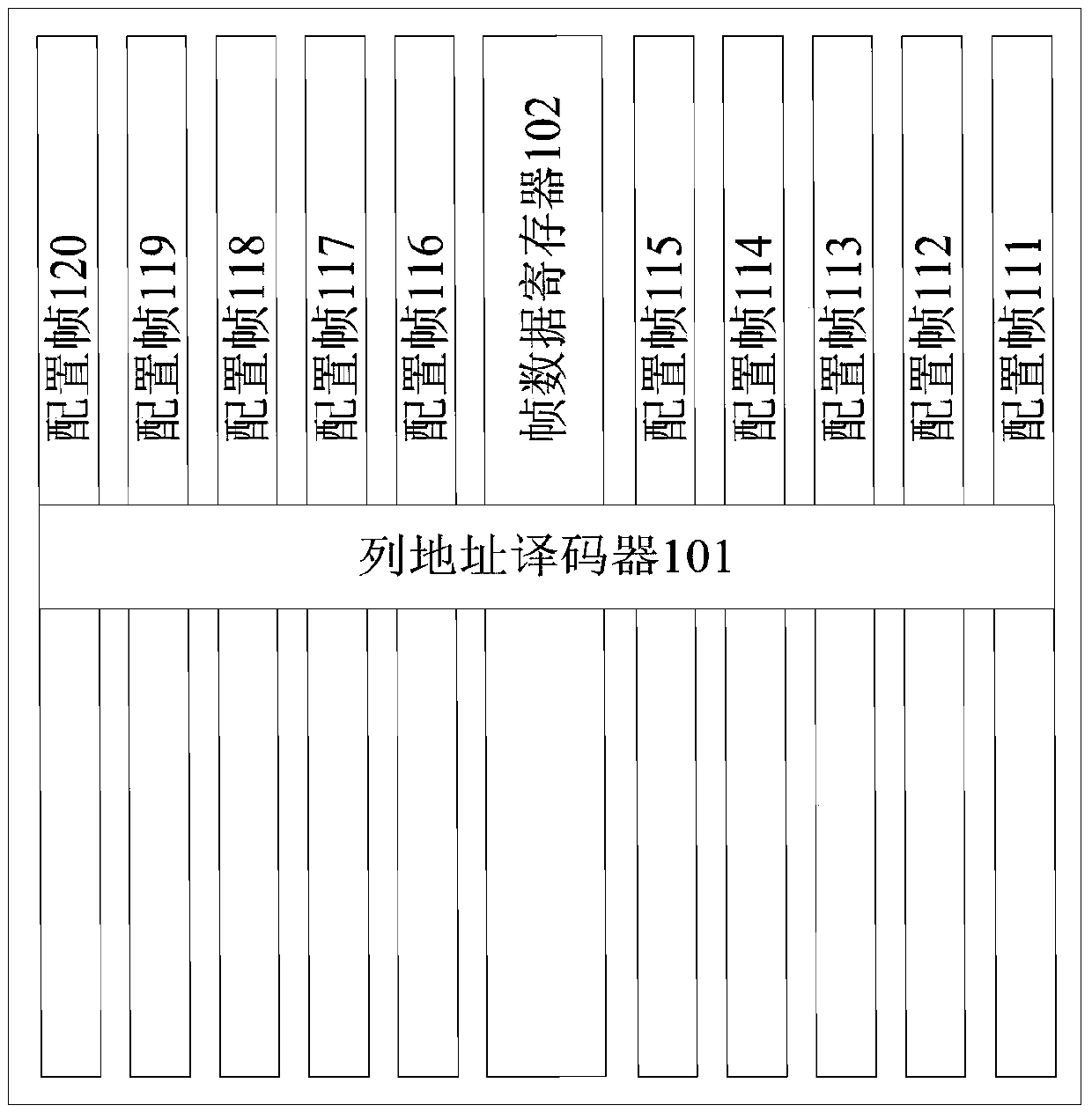
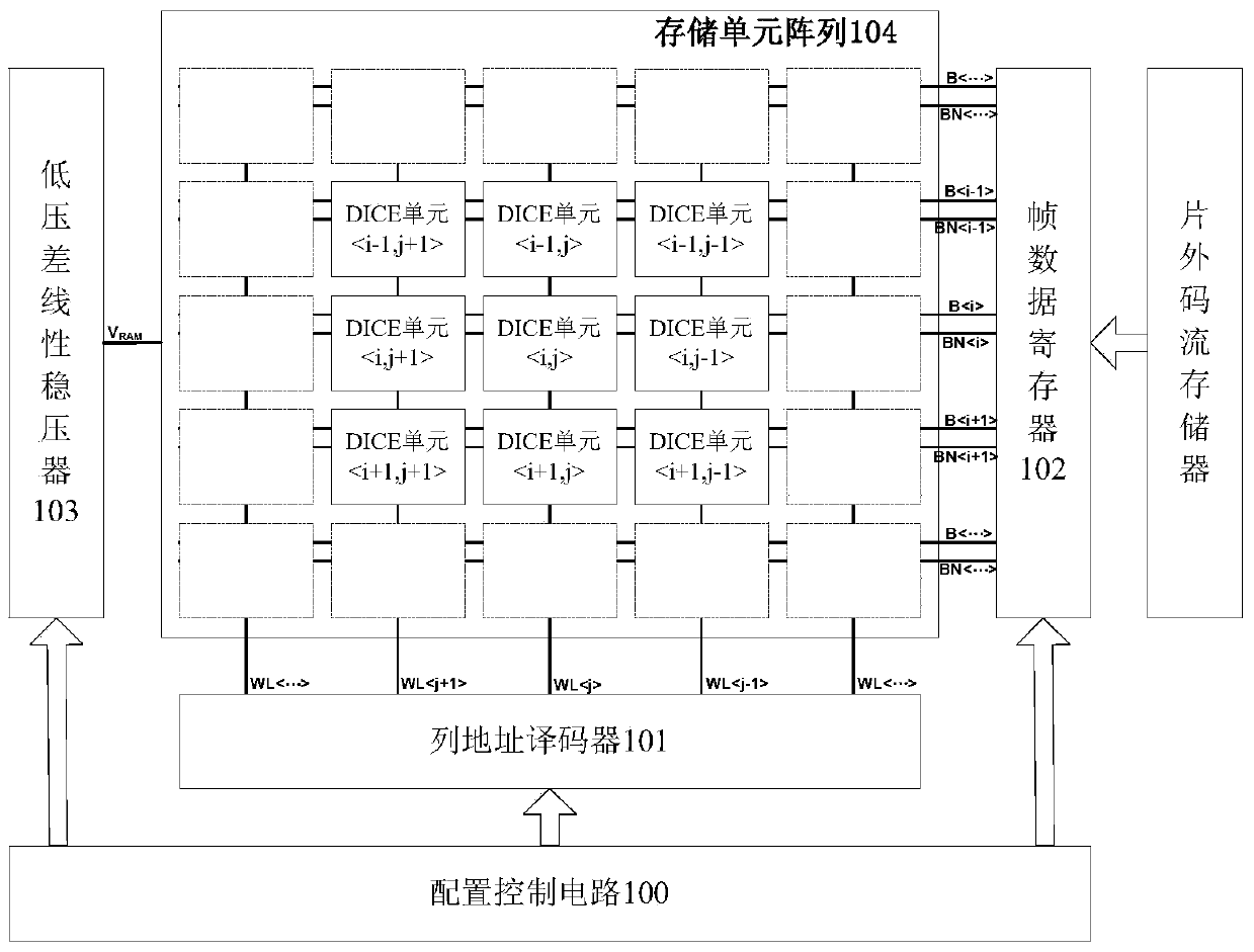
[0034] In order to eliminate, suppress or reduce the impact of single event effects on system functions, the present invention uses dual-node interlocked storage units (hereinafter referred to as DICE units) to carry out radiation-resistant hardening on configuration memory arrays. Such as figure 2 As shown, the configuration memory array of the present invention includes a configuration control circuit 100 , a column address decoder 101 , a frame data register 102 , a low dropout linear regulator 103 , and a memory cell array 104 . The off-chip code stream memory does not belong to the inherent structure of the configuration memory array of the present invention. The configuration control circuit 100 is connected to the column address decoder 101, the frame data register 102, and the low dropout linear voltage regulator 103, and the configuration control circuit 100 is used to control the entire configuration process, including sending power to the low dropout linear voltage...


PUM


Abstract

The invention relates to a reinforcement configuration memory array applicable to an FPGA (Field Programmable Gate Array) for space navigation and a configuration method of the reinforcement configuration memory array, wherein the configuration memory array uses DICEs (Double Interlocked Storage Cells) for realizing single particle reinforcement of the configuration memory array; and the influence of single particles on the configuration memory array is reduced. The configuration method is characterized in that before the configuration memory array is electrified, all configuration memory units are in a 0-write state through a column address decoding circuit and a frame data register; and during electrification, all initial states of all DICEs after the electrification are 0 due to the inductive effect of external work conditions. The logic conflict of an FPGA interconnection matrix after the electrification due to the non-determined state of the configuration memory units is avoided, so that the problem of electrification surge current of the FPGA is effectively solved; the design difficulty of a system using the FPGA is reduced; and the work reliability of the FPGA for space navigation is improved.

Description

technical field [0001] The invention relates to a reinforced configuration memory array and a configuration method suitable for FPGA used in aerospace, and belongs to the technical field of integrated circuits. Background technique [0002] A Field Programmable Logic Gate Array (hereinafter referred to as FPGA) can implement different logic functions according to configuration information. The configuration memory array of traditional aerospace FPGA is as follows: figure 1 As shown, the SRAM unit is used as the storage unit to store the user's configuration information (SRAM-type FPGA for short), and the configuration frame composed of the SRAM unit can be programmed repeatedly indefinitely, so that the application of FPGA has great flexibility, especially suitable for aerospace engineering The characteristic requirements of high reliability, variety and small batch of aerospace devices are widely used in aerospace engineering. [0003] Single event effects such as single ...

Claims


Application Information

Patent Timeline
Patent Type & Authority Patents(China)
IPC IPC(8): G11C16/08G11C16/30
CPCG11C16/08G11C16/30
Inventor 李智赵元富李学武陈雷张彦龙张健
Owner BEIJING MXTRONICS CORP
Why Eureka
Try Eureka